The V.92 standard is an exciting advancement in 56K technology. V.92 offers three functions to enhance the current V.90 standard.
The first enhancement is the "V.PCM-Upstream" technology, which allows a modem's upstream communication to reach speeds of 48,000 bps. The V.90 standard, limited upstream speeds to 31,200 bps.
The second enhancement is Quick Connect, which permits quicker dial-up connections by allowing the modem to remember the line conditions of a service provider that supports V.92. The first time that you connect with your service provider, the modem will perform the full training sequence and store the information it receives. This eliminates the need for the modem to go through the full training sequence during subsequent connection attempts reducing the connection time by 30 - 50%. If the modem is unable to make an optimal connection any time after the initial attempt, the modem will perform the full training sequence.
The third enhancement is the "Modem On Hold" technology, which allows your Internet connection to be suspended when there is an inbound telephone call. You can then return to the connection when the call is completed without losing the connection. If you are connecting to a service provider that supports V.92, you will receive a message informing you of an incoming call. *† In addition, if you subscribe to Caller ID service, the number of the incoming call will be displayed in the computer's message window. You will then have the option to accept the call or to ignore it. If you are connecting to a V.92 server and choose to accept the call, another message will appear notifying you of the length of time that the provider's system will wait on hold before the data connection is terminated. If you are connecting to a server that does not support V.92, you will receive a message informing you of an incoming call. You will then have the option to accept the call or to ignore it. If you choose to accept the call, your data connection will be terminated.
Included on the Installation CD-ROM is the ControlCenter software. The ControlCenter software allows you to easily configure the settings of your new V.92 modem and automatically notifies you of any updates to your modem's code. The manual for the ControlCenter software can be accessed through a link within the ControlCenter interface.
For more information about V.92, go to:
You do not need to qualify your modem for V.92. If you would like to see if there are any updates to your modem's code, go to:
Contact your service provider to find out when they will be updating their servers to include V.92 technology. This modem is backward compatible and will negotiate the highest possible speed when connecting to a service provider.
* You must subscribe to Call Waiting service with your phone company in order to use the "Modem On Hold" enhancement.
† If your incoming calls immediately forward to voice mail, you will not receive this message.
USRobotics and the USRobotics logo are the registered trademarks of U.S. Robotics Corporation.
ITU-T V.92
ITU-T V.90
56K technology (Download up to 56 Kbps, and Upload using V.34)
ITU-T V.34 (Inc 33600)
ITU-T V.32 bis
ITU-T V.32
ITU-T V.22 bis
ITU-T V.22
ITU-T V.23
ITU-T V.21
ITU-T V.42
ITU-T V.42 bis
MNP 2-5
ITU-T V.17
ITU-T V.29
ITU-T V.27ter
ITU-T V.21
EIA 578 Class 1 FAX
EIA 592 Class 2.0 FAX
28000, 29333, 30666, 32000, 33333, 34666, 36000, 37333, 38666, 40000, 41333, 42666, 44000, 45333, 46666, 48000, 49333, 50666, 52000, 53333, 54666, 56000
24000 to 48000
4800, 7200, 9600, 12000, 14400, 16800, 19200, 21600, 24000, 26400, 28800, 31200
28000, 29333, 30666, 32000, 33333, 34666, 36000, 37333, 38666, 40000, 41333, 42666, 44000, 45333, 46666, 48000, 49333, 50666, 52000, 53333, 54666, 56000
4800, 7200, 9600, 12000, 14400, 16800, 19200, 21600, 24000, 26400, 28800, 31200
4800, 7200, 9600, 12000, 14400, 16800, 19200, 21600, 24000, 26400, 28800, 31200, 33600
4800, 7200, 9600, 12000, 14400
300, 1200/75 (V.23), 1200, 2400
2400, 4800, 7200, 9600, 12000, 14400
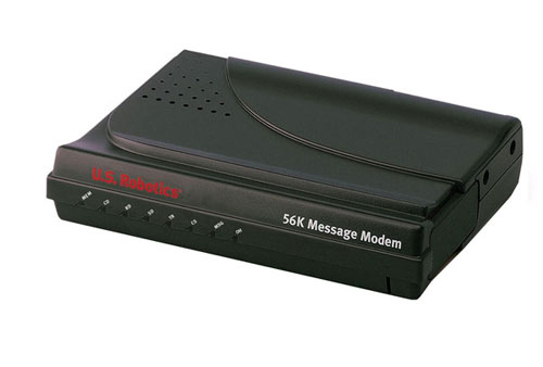
56K Message Modem supports software download through flash memory. You can obtain the latest features by downloading updates quickly and easily.
The 56K Message Modem includes features that allow the user to receive fax and voice messages without the intervention of the PC. The 56K Message Modem features a bank of Flash Memory for this purpose. Messages can be received even when the PC is not turned on. Voice messages can be retrieved from a remote phone.
Note: The 56K Message Modem comes with specially designed application software. This product is not just a normal voice/fax/data modem. The software includes all features needed to manage both the 56K Message Modem in autonomous (independent) mode and normal fax and voice message mode.
Note: The software on the Installation CD-ROM is required to set up Independent Mode. Refer to the instructions in this guide for further information.
MEM/Message Memory
ON indicates that independent mode is activated and the modem will answer any
call even when the PC is off. OFF indicates that independent mode is not activated
and the modem will not answer any call when the PC is off. Blinking rapidly
indicates that self-memory is full.
CD/Carrier Detect
ON if the modem receives a valid data signal (carrier) from a remote modem, indicating that data transmission is possible. Always ON if CD override is ON (&C0).
RD/Receive Data
Flashes when the modem sends result codes or passes received data bits from the remote modem.
SD/Send Data
Flashes when computer sends a data bit to modem.
TR/Data Terminal Ready
ON if modem receives a DTR signal from computer. Always ON (modem ignores DTR) if the DTR override is ON (&DO).
CS/Clear to Send
ON until the modem lowers CTS when transmit data hardware flow control is enabled (&H1, &H3).
MSG/New Message
Blinks red once for each new fax message. Blinks green once for each new voice message. Solid amber indicates that you have received your messages but that they have not been deleted from memory.
OH/Off Hook
ON when modem accesses the phone line. OFF when modem is On Hook.
Write down your new USRobotics modem's serial number, which is located on the white bar code sticker on the modem and on the modem's box. If you ever need to call our Technical Support department, you will need this number to receive assistance.
Shut down your computer and connect the serial cable to the modem and the computer. To find the serial port on the back of your computer, look for COM, MODEM, RS-232, |o|o|, or SERIAL. Do not use the AUX, GAME, LPT, or PARALLEL ports.
Plug one end of the provided phone cord into the ![]() jack on the modem and plug the other end into an analogue phone wall jack. If
you would like to attach a phone to your modem and your model has two phone
jacks, plug your phone into the
jack on the modem and plug the other end into an analogue phone wall jack. If
you would like to attach a phone to your modem and your model has two phone
jacks, plug your phone into the ![]() jack on the modem.
jack on the modem.
Caution: The phone socket you use must be for an analogue phone line. Most office phones are wired through DIGITAL lines. Be sure you know what type of line you have. The modem will be damaged if you use a digital phone line.
Plug the power supply into the ![]() jack on the modem and the other end into an electrical outlet. Plug your headset
into the
jack on the modem and the other end into an electrical outlet. Plug your headset
into the ![]() jack on the modem. Turn
on the modem. The power button is located on the side of the modem.
jack on the modem. Turn
on the modem. The power button is located on the side of the modem.
If the CS light is not on, the modem may not be turned on or plugged in properly. Make sure the modem is turned on and that the power supply is connected between the modem and the electrical outlet.
Note: If a speaker is attached to the modem, the ferrite clamp must be installed around the speaker cable as closely as possible to the modem. Place the speaker cable inside the ferrite clamp and squeeze the ends together until both latches snap into place.
Turn your computer on. After the New Hardware Wizard detects your modem, insert the Installation CD-ROM into your CD-ROM drive. If the CD-ROM autolaunches and the setup program appears, click Cancel or Close to exit. Follow the on-screen prompts to complete the installation. If you are asked for the location of your CD-ROM drive, type the letter of your CD-ROM drive and a colon (D: if your CD-ROM drive letter is D).
Turn your computer on. After you see a message that your new modem has been detected and installed, insert your Installation CD-ROM into your CD-ROM drive. If the CD-ROM autolaunches and the setup program appears, click Cancel or Close to exit. Click Start, select Settings, then click Control Panel. Click View all Control Panel Options in the upper-left corner of your screen. Double-click the System icon. Click Device Manager. Expand Modems by clicking +. Double-click the description of your new modem, then click the Driver tab. Click Update Driver. Select Specify the location of the driver (Advanced). Click Next. Select Removable media. Click Next. Click Next. Click Finish to complete the installation.
Windows NT users must be in administrator mode to properly add any new hardware.
Turn your computer on. Insert your Installation CD-ROM into your CD-ROM drive before you log in. If the CD-ROM autolaunches and the setup program appears, click Cancel or Close to exit. Click Start, point to Settings, and click Control Panel. Double-click Modems. When the Install New Modem screen appears, click Next to have Windows detect your new modem. When your modem is detected, click Change. Click Have Disk. Make sure the location of your CD-ROM drive is selected. Click OK. Select USRobotics. Select USRobotics 56K Message V.92 (non-PnP). Click OK and then Next. Click Finish. The Modems Properties tab will display the COM port that is assigned to your modem. Click Close. If the System Settings Change window appears, click Yes to restart your computer.
Windows 2000 users must be in administrator mode to properly add any new hardware. Your modem will be automatically installed. Follow the update driver procedure below.
Turn your computer on. After you see a message that your
new modem has been installed, insert your Installation CD-ROM into your CD-ROM
drive. If the CD-ROM autolaunches and the setup program appears, click Cancel
or Close to exit. Click Start, select Settings, then click
Control Panel. Double-click the System icon. Click the Hardware
tab. Click Device Manager. Expand Modems by clicking +. Double-click
the description of your new modem or Standard Modem if there is no specific
description, then click the Driver tab. Click Update Driver. Click Next.
Select Search for a suitable driver for my device. Click Next.
Select CD-ROM drive. Click Next. Select Install one of the
other drivers, then click Next. Select USRobotics 56K Message
V.92. Click Next. A Digital Signature Not Found message will appear.
Click Yes*. Click Finish to complete the installation.
Windows XP users must be in administrator mode to properly add any new hardware. Your modem will be automatically installed. Follow the update driver procedure below.
Turn your computer on. Insert your Installation CD-ROM into your CD-ROM drive. If the CD-ROM autolaunches and the setup program appears, click Cancel or Close to exit. Click Start then click Control Panel. If you are not in Classic View, switch to Classic View now by clicking the selection in the upper-left corner of your screen. Double-click the System icon. Click the Hardware tab. Click Device Manager. Expand Modems by clicking +. Double-click the description of your new modem or Standard Modem if there is no specific description, then click the Driver tab. Click Update Driver. Select Install from a Specific Location (Advanced). Click Next. Select Don’t search. I will choose the driver to install. Click Next. Click Have Disk. Type the letter of your CD-ROM drive and a colon (D: if your drive letter is D). Click OK. Select USRobotics 56K Message V.92, then click Next. If you see a warning telling you that this modem has not passed logo testing, click Continue Anyway*. Click Finish.
The ControlCenter software allows you to configure your V.92 modem settings and automatically notifies you of any updates to your modem’s code.
To install the ControlCenter software, eject and reinsert the Installation CD-ROM into your CD-ROM drive. If the Installation CD-ROM interface does not run automatically, click Start and then click Run. In the Run dialogue box, type D:\setup.exe. If your CD-ROM drive uses a different letter, type that letter in place of D. Choose the Software option, and follow the on-screen instructions to install the ControlCenter software.
Internet Call Notification lets you take an incoming voice call without dropping your Internet connection.
To install the Internet Call Notification software, eject and reinsert the
Installation CD-ROM into your CD-ROM drive. If the Installation CD-ROM interface
does not run automatically, click Start and then click Run. In
the Run dialogue box, type D:\setup.exe. If your CD-ROM drive uses a different
letter, type that letter in place of D.
Choose the Software option, select USRobotics Internet
Call Notification, and follow the on-screen instructions to install the Internet
Call Notification software.
The PhoneTools software allows you to use all the voice functionality of your new V.92 modem.
To install the PhoneTools software, eject and reinsert the Installation CD-ROM into your CD-ROM drive. If the Installation CD-ROM interface does not run automatically, click Start and then click Run. In the Run dialogue box, type D:\setup.exe. If your CD-ROM drive uses a different letter, type that letter in place of D. Choose the Software option, select PhoneTools, and then follow the on-screen instructions to install PhoneTools software.
At the Installation CD-ROM interface, click the Support
link. Follow the on-screen instructions to register your modem. If the
Installation CD-ROM interface does not run automatically, click Start
and then click Run. In the Run dialogue box, type D:\setup.exe. If your
CD-ROM drive uses a different letter, type that letter
in place of D. You can also register online at: http://www.usr.com/productreg.
Telephone Handset DTMF Digits for Remote Message Retrieval
Digit(s) Function
|
0
|
1) Stops playback of all voice messages
|
|
|
2) Stops the recording of your outgoing
message
|
|
|
3) Stops playback of your outgoing
message
|
|
1
|
Starts playback of all new messages
|
|
2
|
Starts playback of all stored messages,
new and old
|
|
3
|
Skips to the next voice message
|
|
4 then 4
|
Deletes all old voice messages in
memory
|
Note: To ensure successful message deletion and modem operation, wait until beeping has ceased before hanging up.
|
5
|
Enables/Disables Fax Forwarding
feature
|
|
6
|
Repeats the current voice message
|
|
7
|
Records the personal message
|
|
8
|
Not utilised
|
|
9
|
Repeats the new message count
|
|
*
|
Hangs up the modem
|
|
#
|
Not utilised
|
At any time the user may end the call by pressing the
* key.
The modem will automatically hang up after a period of inactivity.
Caller ID Feature
The Caller ID feature discloses the identification of the caller prior to answering
the call. You can enable/disable this feature through the software application
and are then able to view the calling telephone number from within a dialing
window. Messages retrieved from Independent mode will be stored with Caller
Identification within the software mailbox.
Caller ID must be subscribed from your telephone provider
before this feature can be utilised.
Troubleshooting
If you have any difficulty with your modem, first make sure that it was installed
correctly.
Windows Me, 98, 95
Click Start, Settings, and then Control Panel. Double-click the Modems icon.
In the Modems Properties screen, you should see a description for your new
USRobotics modem. If you do not see a description of your modem, see the
Note at the end of this section. Click the Diagnostics tab. Make sure that the
correct COM port (modem) is selected. Click the More Info button. You
should see a series of commands and responses from the modem. This means that
the installation was a success. If you do not see commands and responses, shut
down and restart your computer. To determine if your modem is functioning properly,
repeat the steps above. If your modem is still not working, refer to the additional
troubleshooting in this Guide.
Windows NT users must be in administrator mode to properly add any new hardware.
Click Start, Settings, and then Control Panel. Double-click the Modems icon. In the Modems Properties screen, you should see a description for your new USRobotics modem. If you do not see your modem listed, shut down and restart your computer. To determine if your modem is functioning properly, try reinstalling your modem. If your modem is still not working, refer to the additional troubleshooting in this Guide.
Windows 2000 users must be in administrator mode to properly add any new hardware.
Click Start, Settings, and then Control Panel. Double-click
the Phone and Modem Options icon. Click the Modems tab. Make sure that
your new USRobotics modem is selected. If you do not see a description of
your modem, see the Note at the end of this section. Click the Properties
button. Click the Diagnostics tab. Click the Query Modem button. You
should see a series of commands and responses from the modem. This means that
the installation was a success. If you do not see commands and responses, shut
down and restart your computer. To determine if your modem is functioning properly,
repeat the steps above. If your modem is still not working, refer to the additional
troubleshooting in this Guide.
Windows XP users must be in administrator mode to properly add any new hardware.
Click Start and then click Control Panel. Click Phone and Modem Options and then click the Modems tab. You should see a description of your new USRobotics modem and a COM port setting. If you do not see a description of your modem, see the Note at the end of this section. Click Modem, highlight the description of your new modem, and click Properties. Click the Diagnostics tab. Click the Query Modem button. You should see a series of commands and responses from the modem. This means that the installation was a success. If you do not see commands and responses, shut down and restart your computer. To determine if your modem is functioning properly, repeat the steps above. If your modem is still not working, refer to the additional troubleshooting in this Guide.
Note: If your modem is not listed and/or you do not see a series of commands and responses, make sure that your cables are attached correctly to your computer. If your modem still does not work, refer to the additional troubleshooting in this Guide. Shut down and restart your computer. To verify that your modem is functioning properly, repeat the steps listed under your specific operating system.
You may be using a COM port that is either already in use or not configured correctly. For the modem to work properly, it must be plugged into an enabled serial port which is assigned to a free COM port. Most computers have two serial ports assigned to COM 1 and COM 2 respectively.
Make sure your COM port is not already in use by another modem. Click Start, Settings (for Windows 2000 only), and Control Panel, and then double-click Phone and Modem Options. Click the Modems tab. Look for a listed modem and check which COM port it is using. If a previous modem is already using the available COM port, you can either use another COM port or uninstall the modem that was installed previously. See your previous modem’s manual for uninstallation instructions. Next, make sure that your COM ports are configured correctly. Right-click the My Computer icon on your desktop. Click Properties. Click the Hardware tab. In the Device Manager section, click the Device Manager button. Look under Ports (COM and LPT). If the Communications ports have yellow exclamation points or red Xs over them, your COM ports may be configured incorrectly. If this is the case, you may need to contact your computer manufacturer. It is also possible that you may be plugging your external modem’s cable into a disabled serial port. Refer to your computer’s manual for information about enabling COM ports. This usually involves altering the BIOS settings and possibly the operating system. You may need to call your computer’s manufacturer to change your BIOS settings if they are incorrect.
Make sure your COM port is not already in use by another modem. Click Start, Settings, and Control Panel, and then double-click Modems. If you have Windows Me and you do not see this icon, be sure to select View All Control Panel Options. Look for another modem listed and if another modem is listed, click the Diagnostics tab to find out which COM port it is using. If a previous modem is already using the available COM port, you can either use another COM port or uninstall the previously installed modem. See your previous modem’s manual for uninstallation instructions. Next, make sure that your COM ports are configured correctly. Right-click the My Computer icon on your desktop. Click Properties. Click the Device Manager tab. Look under Ports (COM and LPT). If the COM ports have yellow exclamation points or red Xs over them, your COM ports may be configured incorrectly. If this is the case and you are not sure how to properly configure your COM ports, contact your computer manufacturer.
It is also possible that you may be plugging your RS232 modem cable into a disabled serial port. Refer to your computer’s manual for information about enabling COM ports. This usually involves altering the BIOS settings and possibly the operating system. You may need to call your computer’s manufacturer to change your BIOS settings if they are incorrect.
Click Start, Settings, and then Control Panel. Double-click Ports. Make sure the port you are plugging the modem into appears in the list. If it does not, the port needs to be added, and possibly enabled in the BIOS. Consult your Windows NT manual for information about adding ports. After you add or enable the port, follow the instructions in this Guide for your operating system.
Your communications software may not function properly if you have more than one version of the software installed or if you are using an older version. We highly recommend using the communications software provided with your modem on the Installation CD-ROM.
Make sure the modem is plugged in and turned on. If it is, check the outlet with another electric device (like a lamp) to be sure that you are getting power. Also, you must use the power supply that came with your modem; other similar-looking power supplies may be of different voltages and could damage your modem. When your modem is properly connected to an electrical outlet, a wall outlet, or a surge protector and is turned on, the CS light on the front panel will be illuminated.
You may not have the correct modem type selected in your software or in Windows. Click Start, Settings (Windows 2000 only), and then Control Panel. When Control Panel opens, click Phone and Modem Options. Click the Modems tab. Here you will see a list of installed modems. You can also add, remove, or view the properties of modems from this window. The USRobotics modem you have installed should be present in the list of installed modems. If none of the modem descriptions in the list matches your USRobotics modem or no modems are listed, your modem is not properly installed. Try reinstalling your modem using the instructions on this Guide for your operating system.
You may not have the correct modem type selected in your software or in Windows. Click Start, Settings, and Control Panel. When Control Panel opens, double-click Modems. Here you will see a list of installed modems. You can also add, remove, or view the properties of modems from this window. The USRobotics modem you have installed should be present in the list of installed modems. If none of the modem descriptions in the list matches your USRobotics modem or no modems are listed, your modem is not properly installed. Try reinstalling your modem using the instructions in this Guide for your operating system.
If you are using Dial-Up Networking, it may not be configured correctly. Check your configuration and make sure you have the correct port selected. Click Start, Control Panel, and double-click Network Connections. Double-click the description of the dial-up networking connection, and select Properties. Make sure that the description in the Connect Using box (under the General tab) matches the description of the modem you are using. If it doesn’t match, select the proper modem description.
If you are using Dial-Up Networking, it may not be configured correctly. Check your configuration and make sure you have the correct port selected. Click Start, point to Settings, and click Network and Dial-up Connections. Make sure that the description in the Connect Using box (under the General tab) matches the description of the modem you are using. If it doesn’t match, select the proper modem description.
If you are using Dial-Up Networking, it may not be installed or configured correctly. Check your configuration and make sure you have the correct port selected. Double-click My Computer. If you are using Windows Me, click Start, point to Settings, then double-click Control Panel. All operating systems should then double-click Dial-Up Networking, right-click the connection you are trying to use, and select Properties. Make sure that the description in the modem box matches the description of the modem you are using. If it doesn’t match, select the proper modem description.
Make sure that you are using the power supply that came with your modem; other similar-looking power supplies may be of different voltages and could damage your modem.
You might have a bad phone cord connected to your modem, or your phone cord
may be plugged into the wrong jack. The phone cord should be plugged into the
jack labelled ![]() on the modem
and directly into the telephone wall jack. Use the phone cord included in your
modem’s box, if possible.
on the modem
and directly into the telephone wall jack. Use the phone cord included in your
modem’s box, if possible.
You may have devices between the modem and the wall jack. There should be no line splitters, fax machines, or other devices between the modem and the telephone wall jack.
You may have plugged your modem’s phone cord into a digital line, which can damage your modem. Contact your phone system administrator if you are unsure whether or not your phone line is digital. If your phone system requires dialing “9” to access an outside line, be sure to add “9” before the number you are dialing.
If you have voice mail provided by your local phone company, your dial tone may be altered when messages are waiting. Retrieve your voice mail to restore your normal dial tone.
You may have a poor connection. All calls are routed differently, so try placing the call again.
Our research has shown that the vast majority of telephone lines can and do support V.90/V.92 connections. The V.90/V.92 protocol allows for connection speeds of up to 56K, but line conditions may affect the actual speeds during a given connection. Due to unusual telephone line configurations, some users will not be able to take full advantage of V.90/V.92 technology at this time. In order to achieve a V.90/V.92 connection:
|
Symbol
|
Meaning
|
Status
|
| MEM | Message Memory | ON indicates that independent mode is activated and the modem will answer any call even when the PC is off. OFF indicates that independent mode is not activated and the modem will not answer any call when the PC is off. Blinking rapidly indicates that self-memory is full. |
| CD | Carrier Detect | ON if the modem receives a valid data signal (carrier) from a remote modem, indicating that data transmission is possible. Always ON if CD override is ON (&C0). |
| RD | Receive Data | Flashes when the modem sends result codes or passes received data bits from the remote modem. |
| SD | Send Data | Flashes when computer sends a data bit to modem. |
| TR | Data Terminal Ready | ON if modem receives a DTR signal from computer. Always ON (modem ignores DTR) if the DTR override is ON (&DO). |
| CS | Clear to Send | ON until the modem lowers CTS when transmit data hardware flow control is enabled (&H1, &H3). |
| MSG | New Message | Blinks red once for each new fax message. Blinks green once for each new voice message. Solid amber indicates that you have received your messages but that they have not been deleted from memory. |
| OH | Off Hook | ON when modem accesses the phone line. OFF when modem is On Hook. |
All defaults are based on the &F1*Hardware Flow Control template loaded in NVRAM when the modem is shipped.
<control key>S
Stop or restart help screens.
<control key>C or <control key>K
Stop help screens.
$ Use in conjunction with D, S, or & commands (or just AT) to display a basic command list; online help.
A Manual Answer goes off hook in answer mode. Pressing any key aborts the operations.
A/ Re-executes the last issued command. Used mainly to redial. This does not require the AT prefix or a Carriage Return.
A> Re-executes the last issued command continuously, until the user intervenes or the command is executed forever. Does not require the AT prefix or a Carriage Return.
Any key Aborts off-hook dial/answer operation and hangs up.
AT Required command prefix, except with A/, +++, and A>. Use alone to test for OK result code.
Bn U.S./ITU-T answer sequence
B0 ITU-T answer sequence
B1 U.S. answer tone
Dn Dials the specified phone number, includes the following:
0-9 Numeric digits
#, * Extended touch-tone pad tones
L Dials the last dialled number
P Pulse (rotary) dial
R Originates call using answer (reverse) frequencies
Sn Dials the phone number string stored at position n (n = 0*3). Phone numbers are stored with the &Zn=s command
T Tone dial
Dn (Comma) Pause, see the definition of the S8 register to which it is linked
; (Semicolon) Return to Command mode after dialling
! (Exclamation point) Flashes the switch hook
/ (Back Slash) Delays for 125 ms. before proceeding with dial string
W Waits for second dial tone (X2 or X4); linked to S6 register
@ (At Symbol) Dials, waits for quiet answer, and continues (X3 or higher)
$ (Dollar Sign) Displays a list of Dial commands
E0 Echo OFF
E1 Modem displays keyboard commands
F0 Local echo ON; modem sends a copy of data, it sends to the remote system to your screen
F1 Local echo OFF; receiving system may send a remote echo of data it receives
H0 Hangs up (goes on hook)
H1 Goes off hook
In Displays the following information:
I0 Four-digit product code
I1 Results of ROM checksum
I2 Results of RAM checksum
I3 Product type
I4 Current modem settings
I5 Stored memory settings
I6 Link diagnostics
I7 Product configuration
I9 Plug and Play information
I11 Extended link diagnostics
Ln Speaker Volume
L0 Lowest Speaker Volume
L1 LowSpeaker Volume
L2 Medium Speaker volume
L3 High Speaker Volume
M0 Speaker always OFF
M1 Speaker ON until CONNECT
M2 Speaker always ON
M3 Speaker ON after dial, until CONNECT
O0 Returns online
O1 Returns online and retrains
Q0 Displays result codes
Q1 Quiet mode; no result codes
Q2 Displays result codes only in Originate mode
Sr.b=n Sets bit .b of register r to n (0/OFF or 1/ON)
Sr=n Sets register r to n
Sr? Displays contents of S-Register r
S$ Displays a list of the S-Registers
Vn Displays verbal/numeric result codes
V0 Numeric codes
V1 Verbal codes
XN Sets result code displayed, default is X4
|
Xn
|
Xn Setting
|
||||
|
Result Codes
|
X0
|
X1
|
X2
|
X3
|
X4
|
|
0/OK
|
*
|
*
|
*
|
*
|
*
|
|
1/CONNECT
|
*
|
*
|
*
|
*
|
*
|
|
2/RING
|
*
|
*
|
*
|
*
|
*
|
|
3/NO CARRIER
|
*
|
*
|
*
|
*
|
*
|
|
4/ERROR
|
*
|
*
|
*
|
*
|
*
|
|
5/CONNECT 1200
|
|
*
|
*
|
*
|
*
|
|
6/NO DIAL TONE
|
|
|
|
*
|
*
|
|
7/BUSY
|
|
|
|
*
|
*
|
|
8/NO ANSWER
|
|
|
|
*
|
*
|
|
9/Reserved
|
|
*
|
*
|
*
|
*
|
|
10/CONNECT 2400
|
|
*
|
*
|
*
|
*
|
|
13/CONNECT 9600
|
|
*
|
*
|
*
|
*
|
|
18/CONNECT 4800
|
|
*
|
*
|
*
|
*
|
|
20/CONNECT 7200
|
|
*
|
*
|
*
|
*
|
|
21/CONNECT 12000
|
|
*
|
*
|
*
|
*
|
|
25/CONNECT 14400
|
|
*
|
*
|
*
|
*
|
|
43/CONNECT 16800
|
|
*
|
*
|
*
|
*
|
|
85/CONNECT 19200
|
|
*
|
*
|
*
|
*
|
|
91/CONNECT 21600
|
|
*
|
*
|
*
|
*
|
|
99/CONNECT 24000
|
|
*
|
*
|
*
|
*
|
|
103/CONNECT 26400
|
|
*
|
*
|
*
|
*
|
|
107/CONNECT 28800
|
|
*
|
*
|
*
|
*
|
|
151/CONNECT 31200
|
|
*
|
*
|
*
|
*
|
|
256/CONNECT 28000
|
|
*
|
*
|
*
|
*
|
|
260/CONNECT 29333
|
|
*
|
*
|
*
|
*
|
|
264/CONNECT 30666
|
|
*
|
*
|
*
|
*
|
|
268/CONNECT 32000
|
|
*
|
*
|
*
|
*
|
|
180/CONNECT 33333
|
|
*
|
*
|
*
|
*
|
|
272/CONNECT 34666
|
|
*
|
*
|
*
|
*
|
|
276/CONNECT 36000
|
|
*
|
*
|
*
|
*
|
|
280/CONNECT 38666
|
|
*
|
*
|
*
|
*
|
|
284/CONNECT 40000
|
|
*
|
*
|
*
|
*
|
|
188/CONNECT 41333
|
|
*
|
*
|
*
|
*
|
|
192/CONNECT 42666
|
|
*
|
*
|
*
|
*
|
|
196/CONNECT 44000
|
|
*
|
*
|
*
|
*
|
|
200/CONNECT 45333
|
|
*
|
*
|
*
|
*
|
|
204/CONNECT 46666
|
|
*
|
*
|
*
|
*
|
|
208/CONNECT 48000
|
|
*
|
*
|
*
|
*
|
|
212/CONNECT 49333
|
|
*
|
*
|
*
|
*
|
|
216/CONNECT 50666
|
|
*
|
*
|
*
|
*
|
|
220/CONNECT 52000
|
|
*
|
*
|
*
|
*
|
|
224/CONNECT 53333
|
|
*
|
*
|
*
|
*
|
|
228/CONNECT 54666
|
|
*
|
*
|
*
|
*
|
|
232/CONNECT 56000
|
|
*
|
*
|
*
|
*
|
|
Adaptive Dialling
|
|
|
*
|
*
|
*
|
|
Wait for 2nd Dial Tone (W)
|
|
|
*
|
|
*
|
|
Wait for Answer (@)
|
|
|
|
*
|
|
|
Fast Dial
|
|
|
*
|
|
*
|
*Requires @ in dial string; replaces NO CARRIER
Yn Selects power-on/reset default configuration
Y0 Use profile 0 setting in NVRAM
Y1 Use profile 1 setting in NVRAM
Y2 Use factory configuration 0 (&F0)
Y3 Use factory configuration 1 (&F1)
Y4 Use factory configuration 2 (&F2)
Z Resets modem
Z0 Resets modem to profile selected by Y command
Z1 Resets modem to profile 0
Z2 Resets modem to profile 1
Z3 Resets modem to factory default profile 0 (&F0)
Z4 Resets modem to factory default profile 1 (&F1)
Z5 Resets modem to factory default profile 2 (&F2)
&$ Displays a list of ampersand (&) commands
&An Enables/disables additional result code subsets, see Xn
&A0 ARQ result codes disabled
&A1 ARQ result codes enabled
&A2 Modulation indicator added
&A3 Protocol indicators added*LAPM/MNP/NONE (error control) and V.42 bis/MNP5 (data compression)
&Bn Manages modem's serial port rate
&B0 Variable, follows connection rate
&B1 Fixed serial port rate
&B2 Fixed in ARQ mode, variable in non-ARQ mode
&Cn Controls Carrier Detect (CD) signal
&C0 CD override
&C1 Normal CD operations
&Dn Controls Data Terminal Ready (DTR) operations
&D0 DTR override
&D1 DTR toggle causes online Command mode
&D2 Normal DTR operations
&D3 Resets on receipt of DTR
&Fn Loads a read-only (non-programmable) factory configuration
&F0 Generic template; no flow control
&F1 Hardware flow control template
&F2 Software flow control template
&Gn Sets Guard Tone
&G0 No guard tone, U.S. and Canada
&G1 550 Hz guard tone, some European countries, requires B0 setting
&G2 1800 Hz guard tone, U.K., requires B0 setting
&Hn Sets Transmit Data (TD) flow control, see also &Rn
&H0 Flow control disabled
&H1 Hardware flow control, Clear to Send (CTS)
&H2 Software flow control, Xon/Xoff
&H3 Hardware and software flow control
&In Sets Receive Data (RD) software flow control, see also &Rn
&I0 Software flow control disabled
&I1 Xon/Xoff signals to your modem and remote system
&I2 Xon/Xoff signals to your modem only
&Kn Enables/disables data compression
&K0 Data compression disabled
&K1 Auto enable/disable
&K2 Data compression enabled
&K3 MNP5 compression disabled
&Mn Sets Error Control (ARQ) for connections at 1200 bps and higher
&M0 Normal mode, error control disabled
&M1 Reserved
&M2 Reserved
&M3 Reserved
&M4 Normal/ARQ
&M5 ARQ mode
&Nn Sets connect speed, if connection cannot be made at this speed, the modem will hang up. When used in conjunction with &Un and &Un is greater than 0, &Nn sets the ceiling connect speed. &Un sets the floor connect speed. (See also the table in the &Un section.)
Note: &N17 through &N39 apply only to V.90 products.
&N0 Connection speed is determined by the remote modem
&N1 300 bps
&N2 1200 bps
&N3 2400 bps
&N4 4800 bps
&N5 7200 bps
&N6 9600 bps
&N7 12,000 bps
&N8 14,400 bps
&N9 16,800 bps
&N10 19,200 bps
&N11 21,600 bps
&N12 24,000 bps
&N13 26,400 bps
&N14 28,800 bps
&N15 31,200 bps
&N16 33,600 bps
&N17 28,000 bps
&N18 29,333 bps
&N19 30,666 bps
&N20 32,000 bps
&N21 33,333 bps
&N22 34,666 bps
&N23 36,000 bps
&N24 37,333 bps
&N25 38,666 bps
&N26 40,000 bps
&N27 41,333 bps
&N28 42,666 bps
&N29 44,000 bps
&N30 45,333 bps
&N31 46,666 bps
&N32 48,000 bps
&N33 49,333 bps
&N34 50,666 bps
&N35 52,000 bps
&N36 53,333 bps
&N37 54,666 bps
&N38 56,000 bps
&Pn Sets pulse (rotary) dial make /break ratio
&P0 Pulse Dialling Disabled (Default for CTR/TBR-21)
&P1 Denmark, Germany, Austria, Finland, Switzerland, Netherlands, Italy, U.S., South Africa, Czech Republic
&P2 France, U.K., Belgium, Ireland, Spain, Portugal, Australia, Asia, Korea
&P3 Norway
&P4 New Zealand
&P5 Japan
&P6 Sweden
&P7 Not Utilised
&Rn Sets Receive Data (RD) hardware low control, Request to Send (RTS), see also &Hn
&R0 Reserved
&R1 Modem ignores RTS
&R2 Received Data to computer only on RTS
&Sn Controls Data Set Ready (DSR) operations
&S0 DSR override; always ON
&S1 Modem controls DSR
&Tn Begins test modes
&T0 Ends testing
&T1 Analogue Loopback
&T2 Reserved
&T3 Local Digital Loopback
&T4 Enables Remote Digital Loopback
&T5 Prohibits Remote Digital Loopback
&T6 Initiates Remote Digital Loopback
&T7 Remote Digital with self-test and error detector
&T8 Analogue Loopback with self-test and error detector
&Un When set above 0, the value chosen from the table sets the floor connect speed (the lowest acceptable connect speed). If a connection cannot be made at or above this speed, the modem will hang up. This command can also be used in conjunction with &Nn.
Note: &U17 through &U39 apply only to V.90 products.
|
&N=0
|
&N>0
|
|
|
&U=0
|
Connects at best possible speed between your modem and the remote modem. | Attempts a connection at the speed defined by &Nn. |
|
Note: These factory default
settings should be sufficient for most users.
|
||
|
&U>0
|
Connects at any speed faster than the value &Un. | Connects at any speed between &Nn and &Un. |
&Un (continued) When set above 0, the value chosen from the table sets the floor connect speed (the lowest acceptable connect speed). If a connection cannot be made at or above this speed, the modem will hang up. This command can also be used in conjunction with &Nn.
&U0 No restrictions on the minimum speed for the connection
&U1 300 bps
&U2 1200 bps
&U3 2400 bps
&U4 4800 bps
&U5 7200 bps
&U6 9600 bps
&U7 12,000 bps
&U8 14,400 bps
&U9 16,800 bps
&U10 19,200 bps
&U11 21,600 bps
&U12 24,000 bps
&U13 26,400 bps
&U14 28,800 bps
&U15 31,200 bps
&U16 33,600 bps
&U17 28,000 bps
&U18 29,333 bps
&U19 30,666 bps
&U20 32,000 bps
&U21 33,333 bps
&U22 34,666 bps
&U23 36,000 bps
&U24 37,333 bps
&U25 38,666 bps
&U26 40,000 bps
&U27 41,333 bps
&U28 42,666 bps
&U29 44,000 bps
&U30 45,333 bps
&U31 46,666 bps
&U32 48,000 bps
&U33 49,333 bps
&U34 50,666 bps
&U35 52,000 bps
&U36 53,333 bps
&U37 54,666 bps
&U38 56,000 bps
&Wn Writes current configuration to NVRAM templates
&W0 Modifies the NVRAM 0 template (Y0)
&W1 Modifies the NVRAM 1 template (Y1)
&Yn Sets break handling
&Y0 Destructive, but does not send break
&Y1 Destructive, expedited
&Y2 Nondestructive, expedited
&Y3 Nondestructive, unexpedited
&Zn=s Writes phone number string s at position n (n = 0*3)
&Zn=L Writes last executed dial string at position n (n = 0*3)
&Zn? Displays the phone number stored at position n (n = 0*3)
&ZL? Displays the last executed dial string
Caller ID Feature
The Caller ID feature discloses the identification of the caller prior to answering
the call. You can enable/disable this feature through the software application
and are then able to view the calling telephone number from within a dialing
window. Messages retrieved from Independent mode will be stored with identification
within the software mailbox.
Caller ID must be subscribed from your telephone provider
before this feature can be utilised.
#CID=n Controls Caller ID feature
#CID=n Controls Caller ID feature
#CID=0 Caller ID disabled
#CID=1 Caller ID enabled with formatted information
#CID=2 Caller ID enabled with unformatted information
+++ Escapes to online-command mode
To change a setting, use the ATSr=n command, where r is the register and n is a decimal value from 0 * 255 (unless otherwise indicated).
|
Register
|
Default
|
Function
|
||||||||||||||||||||||||||||||
|
S0
|
0
|
Sets the number of rings on which to answer in Auto Answer Mode. When set to 0, Auto Answer is disabled | ||||||||||||||||||||||||||||||
|
S1
|
0
|
Counts and stores the number of rings from an incoming call. S0 must be greater than 0 | ||||||||||||||||||||||||||||||
|
S2
|
43
|
Stores the ASCII decimal code for the escape code character Default character is + A value of 128 - 255 disables the escape code |
||||||||||||||||||||||||||||||
|
S3
|
13
|
Stores the ASCII code for the Carriage Return character Valid range is 0 - 127 |
||||||||||||||||||||||||||||||
|
S4
|
10
|
Stores the ASCII decimal code for the Line Feed character Valid range is 0 - 127 |
||||||||||||||||||||||||||||||
|
S5
|
8
|
Stores the ASCII decimal code for the Backspace character
A value of 128*255 disables the Backspace key's delete function |
||||||||||||||||||||||||||||||
|
S6
|
2
|
Sets the number of seconds the modem waits before dialling If Xn is set to X2 or X4, this is the time-out length if there is not a dial tone |
||||||||||||||||||||||||||||||
|
S7
|
60
|
Sets the number of seconds the modem waits for a carrier | ||||||||||||||||||||||||||||||
|
S8
|
2
|
Sets the duration, in seconds, for the pause (,) option in the Dial command | ||||||||||||||||||||||||||||||
|
S9
|
6
|
Sets the required duration, in tenths of a second, of the remote modem's carrier signal before recognition by the modem | ||||||||||||||||||||||||||||||
|
S10
|
14
|
Sets the duration, in tenths of a second, that the modem waits
to hang up after loss of carrier. This guard time allows the modem to distinguish
between a line disturbance from a true disconnect (hang up) by the remote
modem. Note: If you set S10 = 255, the modem will not hang up when carrier is lost Dropping DTR hangs up the modem |
||||||||||||||||||||||||||||||
|
S11
|
72
|
Sets the duration and spacing, in milliseconds, for tone dialling | ||||||||||||||||||||||||||||||
|
S12
|
50
|
Sets the duration, in fiftieths of a second, of the guard time for the escape code sequence (+++) | ||||||||||||||||||||||||||||||
|
S13
|
0
|
Bit-mapped register. Select the bit(s) you want on and set
S13 to the total of the values in the Value column For example: ATS13 = 17 enables bit 0 (value is 1) and bit 4 (value is 16)
|
||||||||||||||||||||||||||||||
|
S14
|
0
|
Reserved | ||||||||||||||||||||||||||||||
|
S15
|
0
|
Bit-mapped register setup. To set the register, see instructions
for S13
|
||||||||||||||||||||||||||||||
|
S14
|
0
|
Reserved | |||||||||||||||||||||||||||
|
S16
|
0
|
Reserved | |||||||||||||||||||||||||||
|
S17
|
0
|
Reserved | |||||||||||||||||||||||||||
|
S18
|
0
|
Test timer for &T loopback testing Sets the time in seconds of testing before the modem automatically times out and terminates the test When set to 0, the timer is disabled Valid range is 1-255 |
|||||||||||||||||||||||||||
|
S19
|
0
|
Sets the duration, in minutes, for the inactivity timer S19=0 disables the timer |
|||||||||||||||||||||||||||
|
S20
|
0
|
Reserved | |||||||||||||||||||||||||||
|
S21
|
10
|
Sets the length, in 10-millisecond units, of breaks sent from the modem to the computer; applies to MNP or V.42 mode only | |||||||||||||||||||||||||||
|
S22
|
17
|
Stores the ASCII decimal code for the Xon character | |||||||||||||||||||||||||||
|
S23
|
19
|
Stores the ASCII decimal code for the Xoff character | |||||||||||||||||||||||||||
|
S24
|
0
|
Reserved | |||||||||||||||||||||||||||
|
S25
|
20
|
Sets the duration, in hundredths of a second, that DTR must
be dropped so that the modem does not interpret a random glitch as a DTR
loss Most users will want to use the default This register is useful for setting compatibility with older systems running under older operating software |
|||||||||||||||||||||||||||
|
S26
|
0
|
Reserved | |||||||||||||||||||||||||||
|
S27
|
0
|
Bit-mapped register setup To set the register, see instructions for S13
|
|
S28
|
0
|
Eliminates the V.32 answer tones for a faster connection 8 Default item, all times are in tenths of seconds 255 Disables all connections except V.32 at 9600 bps |
|||||||||||||||||||||||||||
|
S29
|
20
|
Sets the duration, in tenths of a second, of the V.21 answer mode fallback timer | |||||||||||||||||||||||||||
|
S30
|
0
|
Reserved | |||||||||||||||||||||||||||
|
S31
|
128
|
Reserved | |||||||||||||||||||||||||||
|
S32
|
2
|
Bit-mapped register setup To set the register, see the instructions for S13
|
|
S33
|
0
|
Bit-mapped register setup. To set the register, see the instructions
for S13
|
|
S34
|
0
|
Bit-mapped register setup. To set the register, see the instructions
for S13
|
|
S35-S37
|
|
Reserved |
|
S38
|
0
|
Sets an optional delay, in seconds, before a forced hang-up
and clearing of the Transmit buffer when DTR drops during an ARQ call. This
allows time for a remote modem to acknowledge receipt of all transmitted
data before it is disconnected. The modem immediately hangs up when DTR
drops. This option only applies to connections terminated by dropping DTR. If the modem receives the ATH command, it ignores S38 and immediately hangs up. |
|
S39-S40
|
Reserved | |
|
S41
|
0
|
Reserved |
|
S42
|
0
|
Reserved |
|
+FCLASS=n
|
Sets the mode of operation
|
|
+FCLASS?
|
Displays the current FCLASS mode. (See mode descriptions above) |
|
+FCLASS=?
|
Displays the FCLASS mode options (see mode descriptions above) |
|
+FTS=n
|
Stops the fax transmission Then the modem waits for a specified time before OK appears on screen. The pause is set in 10 millisecond intervals. n is the number of 10 millisecond intervals that pass before OK appears. (n=0-255) |
|
+FRS=n
|
Makes the modem wait for a specified length of silence before
sending OK to the screen The pause is set in10 millisecond intervals. n is the number of 10 millisecond intervals that pass before OK appears. (n=0-255) Note: This command terminates with OK when either the specified amount of silence is detected or when the user types anything (which is ignored). |
|
+FTM=n
|
Transmits data using the modulation specified by n (n = 3, 24, 48, 72, 96, 97, 98, 121, 122, 145, or 146) Note: See the "Screen Messages" table at the end of this section for an explanation of messages that appear in response to this command. |
|
+FRM=n
|
Receives data using the modulation specified by n (n = 3, 24, 48, 72, 96, 97, 98, 121, 122, 145, or 146) Note: See the "Screen Messages" table at the end of this section for an explanation of messages that appear in response to this command. |
|
+FTH=n
|
Transmits data framed in the HDLC protocol using the modulation
specified by n (n = 3, 24, 48, 72, 96, 97, 98, 121, 122, 145, or 146) Note: See the "Screen Messages" table at the end of this section for an explanation of messages that appear in response to this command. |
|
+FRH=n
|
Receives data framed in the HDLC protocol using the modulation
specified by n (n = 3, 24, 48, 72, 96, 97, 98, 121, 122, 145, or 146) Note: See the "Screen Messages" table at the end of this section for an explanation of messages that appear in response to this command. |
|
Numeric Message
|
Text Message
|
Description
|
|
0
|
OK
|
The previous command has been processed successfully. |
|
1
|
CONNECT
|
The modem has just connected to another modem. |
|
2
|
RING
|
Reports the receipt of a network altering ring. |
|
3
|
NO CARRIER
|
No carrier is being received from the modem. |
|
4
|
ERROR
|
The previous command line has not been recognised or was completed abnormally. |
|
5
|
NO DIAL TONE (OPTIONAL)
|
Dial tone was not received within the time-out period. |
|
6
|
BUSY (OPTIONAL)
|
A busy signal was detected. |
|
64
|
CONNECT/FAX (OPTIONAL)
|
The modem has established a fax connection. This response is used only when the fax mode is selected |
The serial interface is a standard developed by the Electronic Industries Association (EIA). It defines the signals and voltages used when data is exchanged between a computer and a modem or serial printer.
The entire standard covers many more functions than are used in most data communications applications. Data is transmitted between the devices over a shielded serial cable with a 25-pin male (DB-25) connector to the modem and a 25-pin, 9-pin, 8-pin, or custom-built connector to the computer.
The use of a shielded cable when connecting a modem to a computer is recommended to ensure minimal interference with radio and television.
Pin assignments are factory-set in the USRobotics modem to match the standard DB-25 assignments in the following table. DB-9 connectors for IBM/AT-compatible computers should be wired at the computer end of the cable as shown in the DB-9 column.
|
DB-25
|
DB-9
|
Circuit
|
Function
|
Computer/Modem
|
|
1
|
-
|
AA
|
Chassis Ground | Both |
|
2
|
3
|
BA
|
Transmitted Data | Computer |
|
3
|
2
|
BB
|
Received Data | Modem |
|
4
|
7
|
CA
|
Request to Send | Computer |
|
5
|
8
|
CB
|
Clear to Send | Modem |
|
6
|
6
|
CC
|
Data Set Ready | Modem |
|
7
|
5
|
AB
|
Signal Ground | Both |
|
8
|
1
|
CF
|
Carrier Detect | Modem |
|
12
|
-
|
SCF
|
Speed Indicate | Modem |
|
20
|
4
|
CD
|
Data Terminal Ready | Computer |
|
22
|
9
|
CE
|
Ring Indicate | Modem |
asynchronous transmission
Data transmission in which the length of time between transmitted characters
may vary. Since the time lapses between transmitted characters are not uniform,
the receiving modem must be signalled as to when the data bits of a character
begin and then they end. The addition of start/stop bits to each character serves
this purpose.
auto answer
In this setting the modem can pick up the phone line when it detects a certain
number of rings. See S-register S0 in the "Technical Reference" section.
autodial
A process where your modem dials a call for you. The dialling process is initiated
by sending an ATDT (dial tone) or ATDP (dial pulse) command followed by the
telephone number to dial. Autodial is used to dial voice numbers. See command
Dn.
baud rate
A term used to measure the speed of an analogue transmission from one point
to another. Although not technically accurate, baud rate is commonly used to
mean bit rate.
binary digit
A 0 or 1, which reflects the use of the binary numbering system. It is
used because the computer recognises either of two states, OFF or ON. The shortened
form of binary digit is bit.
bit rate
This refers to the number of binary digits, or bits, transmitted per second
(bps). It is also referred to as transmission rate. Communications channels
using telephone channel modems are established at set bit rates, commonly 2400,
4800, 9600, 14,400, 28,800 and higher.
bits per second (bps)
This is the bits (binary digits) per second rate. Thousands of bits per
second are expressed as kilobits per second or kbps.
buffer
A memory area set aside to be used as temporary storage during input and
output operations. An example is the modem's command buffer.
byte
A group of binary digits stored and operated upon as a unit. In user documentation,
the term usually refers to 8-bit units or characters. One kilobyte (KB) is equal
to 1,024 bytes or characters; 640 KB indicates 655,360 bytes or characters.
carrier
A tone signifying a connection the modem can alter to communicate data
across telephone lines.
character
A representation, coded in binary digits, of a letter, number, or other
symbol.
characters per second (CPS)
A data transfer rate generally estimated from the bit rate and the character
length. For example, at 2400 bps, 8-bit characters with start/stop bits (for
a total of ten bits per character) will be transmitted at a rate of approximately
240 characters per second (cps). Some protocols, such as error-control protocols,
employ advanced techniques such as longer transmission frames and data compression
to increase cps.
class 1 and 2.0
International standards used between fax application programs and faxmodems
for sending and receiving faxes.
cyclic redundancy checking (CRC)
An error-detection technique consisting of a test performed on each block,
or frame, of data by both sending and receiving modems. The sending modem inserts
the results of its tests in each data block in the form of a CRC code. The receiving
modem compares its results with the received
CRC
code and responds with either a positive or negative acknowledgement.
data communications
A type of communications in which computers are able to exchange data over
an electronic medium.
data compression table
A table containing values assigned for each character during a call under
MNP5 data compression. Default values in the table are continually altered and
built during each call: The longer the table, the more efficient throughput
gained.
data mode
The mode in which the faxmodem is capable of sending and receiving data
files. A standard modem without fax capabilities is always in data mode.
DCE
Data Communications Equipment (or Circuit-Terminating Equipment) is equipment
such as dial-up modems that establish and control the data link via the telephone
network.
default
Any setting assumed, at startup or reset, by the computer's software and
attached devices. The computer or software will use these settings until changed
by the user or other software.
detect phase
In the ITU-T V.42 error-control protocol, the first stage in establishing
if both modems attempting to connect have V.42 capability.
dictionary
The term used for compression codes built by the V.42 bis data compression
algorithm.
digital loopback
A test that checks the modem's RS-232 interface and the cable that connects
the terminal (computer) and the modem. The modem receives data (in the form
of digital signals) from the computer or terminal, and immediately returns the
data to the screen for verification.
digital signals
Signals that are discrete and uniform. In this manual, the term refers
to the binary digits 0 and 1. These signals are in contrast with analogue signals.
DTE
Data Terminal (or Terminating) Equipment is a computer that generates or
is the final destination of data.
duplex
Duplex indicates a communications channel capable of carrying signals in
both directions. See half duplex, full duplex.
Electronic Industries Association (EIA)
This association is a group which defines electronic standards in the U.S.
error control
A variety of techniques that check the reliability of characters (parity)
or blocks of data. V.42 and MNP error-control protocols use error detection
(CRC) and retransmission of flawed frames (ARQ).
facsimile
A method for transmitting the image on a page from one point to another.
This is commonly referred to as fax.
fax mode
The mode in which the faxmodem is capable of sending and receiving files
in a facsimile format. See definitions for V.17, V.27ter, V.29.
flow control
A mechanism that compensates for differences in the flow of data into and
out of a modem or other device. See commands &Hn, &In, &Rn.
frame
A data communications term for a block of data with header and trailer
information attached. The added information usually includes a frame number,
block size data, error-check codes, and Start/End indicators.
full duplex
These signals will flow in both directions at the same time over one line.
In microcomputer communications, may refer to the suppression of the online
local echo.
half duplex
These signals will flow in both directions, but only one way at a time.
In microcomputer communications, may refer to activation of the online local
echo, which causes the modem to send a copy of the transmitted data to the screen
of the sending computer.
Hz
Hertz is a frequency measurement unit used internationally to indicate
cycles per second.
ITU-T
An international organisation that defines standards for telegraphic and
telephone equipment. For example, the Bell 212A standard for 1200 bps communication
in North America is observed internationally as ITU-T V.22. For 2400 bps communication,
most U.S. manufacturers observe V.22 bis.
LAPM
Link Access Procedure for Modems is an error-control protocol defined in
ITU-T Recommendation V.42. Like the MNP protocols, LAPM uses cyclic redundancy
checking (CRC) and retransmission of corrupted data (ARQ) to ensure data reliability.
local echo
A modem feature that enables the modem to display keyboard commands and
transmitted data on the screen. See command En.
MNP
Microcom Networking Protocol is an error-control protocol developed by
Microcom, Inc., and now in the public domain. There are several different MNP
protocols, but the most commonly used one ensures error-free transmission through
error detection (CRC) and retransmission of erred frames.
modem
A device that transmits/receives computer data through a communications
channel such as radio or telephone lines. It also changes signals received from
the phone line back to digital signals before passing them to the receiving
computer.
nonvolatile memory (NVRAM)
A user-programmable random access memory which retains data when power
is turned off. On some modems, it includes four stored phone numbers and the
modem settings.
off/on hook
Modem operations that are the equivalent of manually lifting a phone receiver
(taking it off-hook) and replacing it (going on-hook).
online fall back/fall forward
A feature that allows a high-speed, error-control modem to monitor line
quality and fall back to the next lower speed in a defined range if line quality
diminishes. As line conditions improve, the modem switches up to the next higher
speed.
originate mode
The mode used by your modem when initiating an outgoing call to a destination
modem. The transmit/ receive frequencies are the reverse of the called modem,
which is in answer mode.
parity
A simple error-detection method that checks the validity of a transmitted
character. Character checking has been surpassed by more reliable and efficient
forms of error checking, including V.42 and MNP 2-4 protocols. Either the same
type of parity must be used by two communicating computers, or both may omit
parity.
protocol
A system of rules and procedures governing communications between two or
more devices. Protocols vary, but communicating devices must follow the same
protocol in order to exchange data. The format of the data, readiness to receive
or send, error detection and error correction are some of the operations that
may be defined in protocols.
RAM
Random Access Memory is memory that is available for use when the modem
is turned on, but that clears of all information when the power is turned off.
The modem's RAM holds the current operational settings, a flow control buffer,
and a command buffer.
remote digital loopback
A test that checks the phone link and a remote modem's transmitter and
receiver.
remote echo
A copy of the data received by the remote system, returned to the sending
system, and displayed on the screen. Remote echoing is a function of the remote
system.
ROM
Read Only Memory is permanent memory, which is not user-programmable.
serial transmission
The consecutive flow of data in a single channel. Compare it to parallel
transmissions where data flows simultaneously in multiple channels.
start/stop bits
These signalling bits are attached to a character before and after the
character is transmitted during asynchronous transmission.
terminal
A device whose keyboard and display are used for sending and receiving
data over a communications link. This device differs from a microcomputer or
a
mainframe in that it has little or no internal processing capabilities.
terminal mode
Software mode that allows direct communication with the modem. This mode
is also known as command mode.
throughput
The amount of actual user data transmitted per second without the overhead
of protocol information such as start/stop bits or frame headers and trailers.
Compare it with characters per second.
V.8
The ITU-T standard specification that covers the initial handshaking process.
V.17
An ITU-T standard for making facsimile connections at 14,400 bps, 12,000
bps, 9600 bps, and 7200 bps.
V.21
An ITU-T standard for modems operating in asynchronous mode at speeds up
to 300 bps, full-duplex, on public-switched telephone networks.
V.22
An ITU-T standard for modem communications at 1200 bps, compatible with
the Bell 212A standard observed in the U.S. and Canada.
V.22 bis
An ITU-T standard for modem communications at 2400 bps. The standard includes
an automatic link negotiation fallback to 1200 bps and compatibility with Bell
212A/V.22 modems.
V.23
An ITU-T standard for modem communication at 1200 bps with a 75 bps back
channel.
V.27ter
An ITU-T standard for facsimile operations that specifies modulation at
4800 bps, with fallback to 2400 bps.
V.29
An ITU-T standard for facsimile operations that specifies modulation at
9600 bps, with fallback to 7200 bps.
V.32
An ITU-T standard for modem communications at 9600 bps and 4800 bps. V.32
modems fall back to 4800 bps when line quality is impaired.
V.32 bis
An ITU-T standard that extends the V.32 connection range: 4800, 7200, 9600,
12,000, and 14,400 bps. V.32 bis modems fall back to the next lower speed when
line quality is impaired, fall back further as necessary, and also fall forward
(switch back up) when line conditions improve.
See online fall back/fall forward.
V.34
An ITU-T standard that currently allows data rates as high as 28,800 bps
and 33,600bps.
V.42
An ITU-T standard for modem communications that defines a two-stage process
of detection and negotiation for LAPM error control.
V.42 bis
An extension of ITU-T V.42 that defines a specific data compression scheme
for use during V.42 connections.
V.90/V.92
The ITU-T standard for 56 Kbps modem communications.
Xmodem
The first of a family of error control software protocols used to transfer
files between modems. These protocols are in the public domain and are available
from many bulletin board services.
Xon/Xoff
Standard ASCII control characters used to tell an intelligent device to
stop/resume transmitting data.
Ymodem
An error-checking protocol that can send several files of data at a time
in 1024-byte (1K) blocks. This protocol can use either checksums or CRC for
error checking.
Ymodem G
This is similar to the Ymodem, except it relies on the modem for error
checking, which makes it faster.
Zmodem
This is similar to Xmodem and Ymodem, except it includes batch transfer,
the ability to recover from a partially complete transfer, an autostart feature,
and improved efficiency.
We declare under our sole responsibility that the USRobotics 56K Faxmodem is in conformity with the following standards or other normative documents:
CE Compliance
We, USRobotics Corporation of 935 National Parkway, Schaumburg, Illinois,
60173-5157 USA, declare under our sole responsibility that the product, 56K
Message Modem, Model 5668, to which this declaration relates, is in conformity
with the following standards and/or other normative documents.
EN60950
EN55022
EN55024
EN61000-3-2
EN61000-3-3
We hereby declare that the above named product is in conformity with the essential requirements and other relevant provisions of Directive 1999/5/EC.
The conformity assessment procedure referred to in Article 10(3) and detailed in Annex II of Directive 1999/5/EC has been followed.
Network Compatibility Declaration
This equipment is designed to work satisfactorily on all European Union PSTN
networks.
This equipment is supplied with a suitable PSTN connector for the country in which it was supplied. If it is required to use this equipment on a different network to the one for which it was supplied, the user is advised to contact the vendor for guidance regarding connection.
FRS Europe BV.
Draaibrugweg 2
1332 AC Almere
The Netherlands
1.0 GENERAL TERMS:
1.1 This Limited Warranty is extended only to the original end-user purchaser
(CUSTOMER) and is not transferable.
1.2 No agent, reseller, or business partner of USRobotics Corporation (U.S.
ROBOTICS) is authorised to modify the terms of this Limited Warranty on behalf
of USRobotics.
1.3 This Limited Warranty expressly excludes any product that has not been purchased
as new from USRobotics or its authorised reseller.
1.4 This Limited Warranty is only applicable in the country or territory where
the product is intended for use (As indicated by the Product Model Number and
any local telecommunication approval stickers affixed to the product).
1.5 USRobotics warrants to the CUSTOMER that this product will be free from
defects in workmanship and materials, under normal use and service, for TWO
(2) YEARS from the date of purchase from USRobotics or from its authorised
reseller.
1.6 USRobotics sole obligation under this warranty shall be, at USRobotics
sole discretion, to repair the defective product or part with new or reconditioned
parts; or to exchange the defective product or part with a new or reconditioned
product or part that is the same or similar; or if neither of the two foregoing
options is reasonably available, USRobotics may, at its sole discretion,
provide a refund to the CUSTOMER not to exceed the latest published USRobotics
recommended retail purchase price of the product, less any applicable service
fees. All products or parts that are exchanged for replacement will become the
property of USRobotics.
1.7 USRobotics warrants any replacement product or part for NINETY (90) DAYS
from the date the product or part is shipped to Customer.
1.8 USRobotics makes no warranty or representation that this product will
meet CUSTOMER requirements or work in combination with any hardware or software
products provided by third parties.
1.9 USRobotics makes no warranty or representation that the operation of
the software products provided with this product will be uninterrupted or error
free, or that all defects in software products will be corrected.
1.10 USRobotics shall not be responsible for any software or other CUSTOMER
data or information contained in or stored on this product.
2.0 CUSTOMER OBLIGATIONS
2.1 CUSTOMER assumes full responsibility that this product meets CUSTOMER specifications
and requirements.
2.2 CUSTOMER is specifically advised to make a backup copy of all software provided
with this product.
2.3 CUSTOMER assumes full responsibility to properly install and configure this
product and to ensure proper installation, configuration, operation and compatibility
with the operating environment in which this product is to function.
2.4 CUSTOMER must furnish USRobotics a dated Proof of Purchase (copy of original
purchase receipt from USRobotics or its authorised reseller) for any warranty
claims to be authorised.
3.0 OBTAINING WARRANTY SERVICE:
3.1 CUSTOMER must contact USRobotics Technical Support or an authorised U.S.
ROBOTICS Service Centre within the applicable warranty period to obtain warranty
service authorisation.
3.2 Customer must provide Product Model Number, Product Serial Number and dated
Proof of Purchase (copy of original purchase receipt from USRobotics or its
authorised reseller) to obtain warranty service authorisation.
3.3 For information on how to contact USRobotics Technical Support or an
authorised USRobotics Service Centre, please see the U.S ROBOTICS corporate
Web site at: www.usr.com
3.4 CUSTOMER should have the following information / items readily available
when contacting USRobotics Technical Support:
4.0 WARRANTY REPLACEMENT:
4.1 In the event USRobotics Technical Support or its authorised USRobotics
Service Centre determines the product or part has a malfunction or failure attributable
directly to faulty workmanship and/or materials; and the product is within the
TWO (2) YEAR warranty term; and the CUSTOMER will include a copy of the dated
Proof of Purchase (original purchase receipt from USRobotics or its authorised
reseller) with the product or part with the returned product or part, then U.S.
ROBOTICS will issue CUSTOMER a Return Material Authorisation (RMA) and instructions
for the return of the product to the authorized USRobotics Drop Zone.
4.2 Any product or part returned to USRobotics without an RMA issued by U.S.
ROBOTICS or its authorised USRobotics Service Centre will be returned.
4.3 CUSTOMER agrees to pay shipping charges to return the product or part to
the authorised USRobotics Return Centre; to insure the product or assume
the risk of loss or damage which may occur in transit; and to use a shipping
container equivalent to the original packaging.
4.4 Responsibility for loss or damage does not transfer to USRobotics until
the returned product or part is received as an authorised return at an authorised
USRobotics Return Centre.
4.5 Authorised CUSTOMER returns will be unpacked, visually inspected, and matched
to the Product Model Number and Product Serial Number for which the RMA was
authorised. The enclosed Proof of Purchase will be inspected for date of purchase
and place of purchase. USRobotics may deny warranty service if visual inspection
of the returned product or part does not match the CUSTOMER supplied information
for which the RMA was issued.
4.6 Once a CUSTOMER return has been unpacked, visually inspected, and tested
USRobotics will, at its sole discretion, repair or replace, using new or
reconditioned product or parts, to whatever extent it deems necessary to restore
the product or part to operating condition.
4.7 USRobotics will make reasonable effort to ship repaired or replaced product
or part to CUSTOMER, at USRobotics expense, not later than TWENTY ONE (21)
DAYS after USRobotics receives the authorized CUSTOMER return at an authorised
USRobotics Return Centre.
4.8 USRobotics shall not be liable for any damages caused by delay in delivering
or furnishing repaired or replaced product or part.
5.0 LIMITATIONS
5.1 THIRD-PARTY SOFTWARE: This USRobotics product may include or be bundled
with third-party software, the use of which is governed by separate end-user
license agreements provided by third-party software vendors. This USRobotics
Limited Warranty does not apply to such third-party software. For the applicable
warranty refer to the end-user license agreement governing the use of such software.
5.2 DAMAGE DUE TO MISUSE, NEGLECT, NON-COMPLIANCE, IMPROPER INSTALLATION, AND/OR
ENVIRONMENTAL FACTORS: To the extent permitted by applicable law, this U.S.
ROBOTICS Limited Warranty does not apply to normal wear and tear; damage or
loss of data due to interoperability with current and/or future versions of
operating system or other current and/or future software and hardware; alterations
(by persons other than USRobotics or authorized USRobotics Service Centres);
damage caused by operator error or non-compliance with instructions as set out
in the user documentation or other accompanying documentation; damage caused
by acts of nature such as lightning, storms, floods, fires, and earthquakes,
etc. Products evidencing the product serial number has been tampered with or
removed; misuse, neglect, and improper handling; damage caused by undue physical,
temperature, or electrical stress; counterfeit products; damage or loss of data
caused by a computer virus, worm, Trojan horse, or memory content corruption;
failures of the product which result from accident, abuse, misuse (including
but not limited to improper installation, connection to incorrect voltages,
and power points); failures caused by products not supplied by USRobotics;
damage cause by moisture, corrosive environments, high voltage surges, shipping,
abnormal working conditions; or the use of the product outside the borders of
the country or territory intended for use (As indicated by the Product Model
Number and any local telecommunication approval stickers affixed to the product).
5.3 TO THE FULL EXTENT ALLOWED BY LAW, THE FOREGOING WARRANTIES AND REMEDIES
ARE EXCLUSIVE AND ARE IN LIEU OF ALL OTHER WARRANTIES, TERMS, OR CONDITIONS,
EXPRESS OR IMPLIED, EITHER IN FACT OR BY OPERATION OF LAW, STATUTORY OR OTHERWISE,
INCLUDING WARRANTIES, TERMS, OR CONDITIONS OF MERCHANTABILITY, FITNESS FOR A
PARTICULAR PURPOSE, SATISFACTORY QUALITY, CORRESPONDENCE WITH DESCRIPTION, AND
NON-INFRINGEMENT, ALL OF WHICH ARE EXPRESSLY DISCLAIMED. USRobotics NEITHER
ASSUMES NOR AUTHORISES ANY OTHER PERSON TO ASSUME FOR IT ANY OTHER LIABILITY
IN CONNECTION WITH THE SALE, INSTALLATION, MAINTENANCE, WARRANTY, OR USE OF
ITS PRODUCTS.
5.4 LIMITATION OF LIABILITY. TO THE FULL EXTENT ALLOWED BY LAW, USRobotics
ALSO EXCLUDES FOR ITSELF AND ITS SUPPLIERS ANY LIABILITY, WHETHER BASED IN CONTRACT
OR TORT (INCLUDING NEGLIGENCE), FOR INCIDENTAL, CONSEQUENTIAL, INDIRECT, SPECIAL,
OR PUNITIVE DAMAGES OF ANY KIND, OR FOR LOSS OF REVENUE OR PROFITS, LOSS OF
BUSINESS, LOSS OF INFORMATION OR DATA, OR OTHER FINANCIAL LOSS ARISING OUT OF
OR IN CONNECTION WITH THE SALE, INSTALLATION, MAINTENANCE, USE, PERFORMANCE,
FAILURE, OR INTERRUPTION OF ITS PRODUCTS, EVEN IF USRobotics OR ITS AUTHORISED
RESELLER HAS BEEN ADVISED OF THE POSSIBILITY OF SUCH DAMAGES, AND LIMITS ITS
LIABILITY TO REPAIR, REPLACEMENT, OR REFUND OF THE PURCHASE PRICE PAID, AT U.S.
ROBOTICS OPTION. THIS DISCLAIMER OF LIABILITY FOR DAMAGES WILL NOT BE AFFECTED
IF ANY REMEDY PROVIDED HEREIN SHALL FAIL OF ITS ESSENTIAL PURPOSE.
6.0 DISCLAIMER: Some countries, states, territories or provinces do not allow
the exclusion or limitation of implied warranties or the limitation of incidental
or consequential damages for certain products supplied to consumers, or the
limitation of liability for personal injury, so the above limitations and exclusions
may be limited in their application to CUSTOMER. When the implied warranties
are not allowed by law to be excluded in their entirety, they will be limited
to the TWO (2) YEAR duration of this written warranty. This warranty gives CUSTOMER
specific legal rights, which may vary depending on local law.
7.0 GOVERNING LAW: This Limited Warranty shall be governed by the laws of the
State of Illinois, U.S.A. excluding its conflicts of laws principles and excluding
the United Nations Convention on Contracts for the International Sale of Goods.
USRobotics Corporation
935 National Parkway
Schaumburg, IL 60173
U.S.A
If you have not fixed your problem after trying the suggestions in the “Troubleshooting” section, you can receive additional help via one of these convenient resources:
Many of the most common difficulties users experience have been addressed in the FAQ and Troubleshooting Web pages for your specific product. Your product number is USR995668B. You may need to know this to obtain information on the USRobotics Web site. Go to: http://www.usr.com/support
Technical questions about USRobotics modems can also be answered by technical
support specialists.
| Country | Telephone | Online | Hours |
| Middle East (English) | +44 870 844 4546 | me_modemsupport@usr.com | 8:00 A.M.– 5:00 P.M. GMT Monday – Friday |