
Contents:
Web User Interface
Quick Setup
Service Provider Settings
Network
Firewall
Tools
Statistics
USRobotics SureConnect™ ADSL Ethernet/USB Router User Guide
Windows 95, 98, NT 4.0, Me, 2000, XP or later, Mac and Linux
Web User Interface
Overview
The Web User Interface (WUI) is one of three router user interfaces. The other interfaces are the Terminal User Interface (TUI) and Command Line Interface (CLI). Each interface allows you to set up, modify, and view router configuration variables and operational data.
The Web User Interface is a system of graphical menus. Menu pages control router parameters and provide information about them. The WUI organizes these router parameters into six topics. Here are the six topics, in the order that the WUI displays them...
| • Quick Setup | • Firewall Settings |
| • Service Provider Settings | • Tools |
| • Network Settings | • Statistics |
This part of the manual discusses all but the Quick Setup topic. You’ll find information on using the Quick Setup feature in the Quick Installation Guide.
This manual begins topic discussions with a picture of the top-level menu screen. A description of screen terms and procedures follows each screen shot. Either text or a table defines screen variables. Afterward, summarized, step-by-step procedures often follow.
Selecting Topics. When you look at a menu page, notice the divider tabs at the very top of the page. You can access any of the six router configuration and information topics by clicking on its tab. The graphic below portrays the six divider tabs as they appear on a menu.
| |
|
|
Divider Tabs |
|

Configuration Options. Most menus present configuration options and prompt you for a response. For example, the screen may help you to set up service provider, network or firewall parameters. Some menus offer additional or more specific options by presenting lower-level (secondary) screens. The bottom of many screens includes a set of graphical buttons. Clicking one of the buttons with your mouse determines the disposition of options on the page. For example…
| • Add | • Delete |
| • Modify | • Disable |
| • Configure XXX | • Erase |
Selecting or Enabling Features. You can select menu options by clicking radio buttons or checking boxes on the screen. In either case, use your mouse to make selections. Radio buttons allow you to select only one of several options. Checkboxes allow you to enable none, one or many features. The graphic below includes examples of both radio buttons and checkboxes.
|
Radio Buttons |
|
|
Checkboxes |
Accessing the Web User Interface
Your router includes the SureConnect ADSL Web Utility. This Web utility displays after you complete installation.
To access the Web User Interface, follow these steps…
- Install your router according to the Quick Installation Guide.
- Connect the router to the Ethernet or USB port on your PC.
- Open a Web browser and go to IP address http://192.168.1.1. (Otherwise, go to the LAN IP designated for the router's management port.)
- At the prompt, type in your user name and password. The default user name is "root." The default password is "12345." (Don't type the quotation marks or period.)
Service Provider Setting Page
WAN Setup
Use this menu option to configure an ISP connection. ADSL employs Asynchronous Transfer Mode (ATM) protocol to send data to the Internet Service Providers. An ATM circuit uses Permanent Virtual Circuit (PVC) as pathway to identify and route modem data. The USRobotics Ethernet/USB Router supports multiple PVC connections for multiple ISPs.
To configure a PVC…
- Delete any connection that you don’t need.
- Select the PVC in the Current ATM PVC List.
- Click Delete.
- Click the connection type recommended by your ISP. Choose a mode: RFC1483 Bridged, RFC1483 Routed, PPPoE, PPPoA or MER.
If you chose RFC1483 Bridged mode, follow these steps…
- Enter VPI / VCI values.
- Click the radio button for the desired encapsulation mode: LLC/SNAP or VC Multiplexing.
- Network Settings: Be sure that options Enable NAPT and Enable DHCP are not selected.
- Click Add.
If you chose RFC1483 Routed mode, follow these steps…
- Enter the WAN IP Address for your ISP.
- Enter the WAN Subnet Mask for your ISP.
- Enter VPI / VCI values.
- Click the radio button for the desired encapsulation mode: LLC/SNAP or VC Multiplexing.
- Network Settings: Be sure that options Enable NAPT and Enable DHCP remain selected.
- Click Add.
If you chose PPPoE mode, follow these steps…
- Enter Username and Password.
- Select “Direct” Dialing mode. Only choose “Auto” if you prefer to start and stop your connection while data is flowing.
- Enter the IDLE Timeout: This function adjusts the number of minutes of no traffic before the connection terminates. The idle timeout connection terminates when you select “Auto” Dialing Mode.
- Select the Authentication method: Chap or PAP or MS-CHAP.
- Enter VPI / VCI values.
- Click the radio button for the desired encapsulation mode: LLC/SNAP or VC Multiplexing.
- Network Settings: Be sure that options Enable NAPT and Enable DHCP remain selected.
- Click Add.
If you chose PPPoA mode, follow these steps…
- Enter Username and Password.
- Select the Authentication method: Chap or PAP or MS-CHAP.
- Enter VPI / VCI values.
- Click the radio button for the desired encapsulation mode: LLC/SNAP or VC Multiplexing.
- Network Settings: Be sure that options Enable NAPT and Enable DHCP remain selected.
- Click Add.
If you chose MER mode, follow these steps…
- Enter the WAN IP Address for your ISP.
- Enter WAN Subnet Mask for your ISP.
- Enter VPI / VCI values.
- Click the radio button for the desired encapsulation mode: LLC/SNAP or VC Multiplexing.
- Network Settings: Be sure that options Enable NAPT and Enable DHCP remain selected.
- Click Add.
Proceed to the Tools Menu to save your changes.
ADSL Standard
The ADSL Standard menu configures the ADSL protocol. You’ll find four supported protocols: Multi-mode, T1.413, G.dmt and G.lite. Your ISP determines the protocol to use. In most cases, Multi-mode should allow a connection to the ISP.
PPPoE Relay
PPPoE Relay protocol supports multiple PPPoE sessions through the router, on a LAN interface, over an RFC1483 Bridged PVC. The router supports multiple sessions by maintaining a mapping table. In this table, each entry represents one session. The Client / Server side MAC address and the Session Id provide the basis for the mapping. Refer to WAN setup instructions on configuring PPPoE. The PPPoE Relay option requires an ATM PVC (server) and a LAN interface (client). The client initiates a PPPoE session with the server via a third-party PPPoE client. Follow these steps…
- Configure the client and server.
- Click Enable to start the relay function.
NAPT Bridge
This screen provides the option of enabling or disabling MER PVC. From this screen, you can also change this PVC’s ATM values. The MER Interface is an RFC1483 Bridged PVC, terminated in the router with a static public address. The ISP provides the static public address. This type PVC operates with Network Address Translation (NAT) and DHCP. These protocols allow the router to serve LAN users with private addresses.
Bridging
You can group router LAN interfaces. Grouping allows forwarding of their Ethernet frames to an ATM interface. The USRobotics Ethernet/USB Router defaults to bridging on three ports: ETH1, ETH2 and USB. The router bridges these ports to the atm0 interface or the first PVC under WAN SETUP.
To change the grouping…
- Click Erase All.
- Click Interfaces.Choose the desired LAN Interfaces.
- Click Apply.
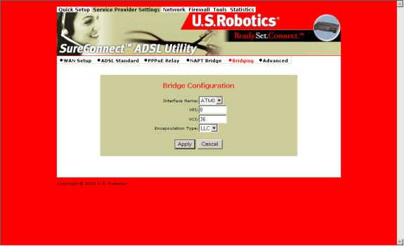
To bind the LAN Interfaces to an ATM interface, select “Add Bridge.”
- Select the ATM Interface from the Interface Name drop-down list.
- Enter the VPI / VCI to which this ATM circuit belongs. Refer to WAN Setup for information on setting up a bridged PVC.
- Click Apply.
- At the List of Bridge Entries, click Enable. This action activates packet forwarding.
Advanced
Use the Advanced Interface menu to configure LAN, PPP and ATM interfaces. Follow these steps…
- Select the Interface Name.
- Set the IP and Subnet Mask by clicking Configure Interface. Some interfaces allow the option of changing interface status.
Interfaces:
• Interface mer0 usage is reserved. Its status is always Down.
• Interface ADSL0 is the ADSL SNMP interface.
• Interface lo0 is the loopback interface. When you perform an OAM loopback, the status field displays UP.
• Interfaces Atm0 to Atm 7 display the interfaces configured for RFC1483 bridged mode or RFC 1483 routed mode.
• Interfaces pppo to ppp7 display the interfaces configured for PPPoE or PPPoA.
Parameters:
• Dynamic IP address from DHCP: Selecting this option allows the DHCP Server to assign the IP address.
• Static IP address:
Selects the IP address to be statically assigned.
• Interface: The name of the selected interface.
• IP address: The IP address of the selected interface.
• Subnet Mask: The subnet mask of the selected interface.
• MTU: Sets the maximum transmission unit of the interface. The MTU limits the size of packets that transmit on an interface. Not all interfaces support the MTU parameter. Some interfaces, like Ethernet, have range restrictions (80 - 1500).
• Speed: Auto, 10 Mbps, or 100 Mbps.
• State: Enable and Disable. When you set an interface to Disable, the system won’t attempt to transmit messages through that interface. When you set an interface to Enable, you can transmit messages through the interface.
Use the Advance–VCC menu to add and delete ISP connections. This menu also includes options to enter ATM Quality of Service (Qos) parameters. The Advance–VCC menu operates similarly to the WAN Setup menu.
The menu only supports Data type ATM circuits.
To list the Quality of Service setting per PVC, click the Show QOS Settings button.
Advance–VCC Menu Add Parameters
| Parameter |
Definition |
|
VPI |
Virtual Path Identifier (VPI) that identifies the ATM connection. The vpi is an integer that ranges from 0 to 4,095. |
|
VCI |
Virtual Channel Identifier (VCI) that identifies the ATM connection. The VCI is an integer that ranges from 0 to 65,535. |
| Peak Cell Rate (Cells/sec) |
Maximum rate for sending cells to the network. |
| Average Cell Rate
(Cells/sec) |
Maximum sustainable or average rate for sending cells to the network. Average Cell Rate specifies bandwidth utilization. This value must always be less than or equal to Peak Cell Rate. |
|
Burst Size (cells) |
Maximum number of cells that the user can send at peak rate in a burst. We measure burst size from within a sustainable rate. |
|
CDVT (cells) |
Constrains the number of cells the user can send to the network at the maximum line rate. |
|
Type |
Only data support – NO voice. |
|
Service Type cbr Constant Bit Rate |
Supports real-time applications that require a fixed amount of bandwidth. These applications, such as a video stream, produce data at regular intervals. The user can specify how much bandwidth that he wishes to reserve. |
|
rtvbr Real Time Variable Bit Rate |
Supports time-sensitive applications such as voice. Varies the rate at which cells arrive. |
|
Nrtvbr Non Real Time Variable Bit Rate: |
Supports applications that have no constraints on delay and delay variation, but still have variable-rate and bursty traffic characteristics. |
|
Ubr Unspecified Bit Rate |
Best effort service that does not require tightly constrained delay and delay variation. UBR provides no specific quality of service or guaranteed throughput. |
Advance–PPPOE. Use Advance–PPPoE to connect to, or disconnect from a PPPoE server. Click Start to use the connection. Click Stop to disconnect. The menu also includes two other button options. Click Default to make the ISP connection your default connection. Click Delete to delete the connection.

Advance–PPPOA. Use Advance–PPPoA to connect to, or disconnect from a PPPoA server. Click Start to use the connection. Click Stop to disconnect. The menu also includes two other button options. Click Default to make the ISP connection your default connection. Click Delete to delete the connection.
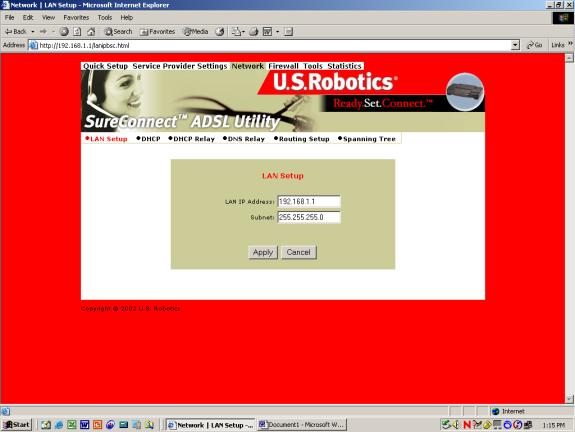
LAN Setup
Use LAN Setup to set the router’s IP Address and Subnet Mask. The LAN IP address allows you to connect the router to your LAN. This address also allows you to manage the router from your LAN. A LAN (Local Area Network) connects computers in the same building or area.
Subnet masks split one network into a set of mini networks or subnets. Subnetting helps to reduce traffic on each subnet. Subnetting also makes the network more manageable. Each subnet functions as if it were an independent network.
To set up the LAN…
- Enter the LAN IP Address for the router to use on the network.
- Enter the Subnet Mask for the network that the router connects to.
- Click Apply.
NOTICE. The LAN setup process changes the IP address of the Web User Interface. The apply action causes the router to save your current configuration and then restart. After the router restarts, you'll have to reapply to the Web User Interface using a new IP address.
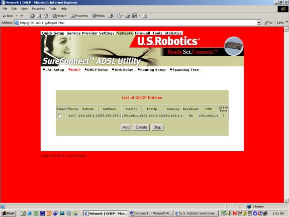
DHCP
DHCP stands for Dynamic Host Configuration Protocol. This protocol dynamically assigns IP addresses and related information to Local Area Network (LAN) nodes. For temporarily connected network users, DHCP provides safe, reliable, and simple TCP/IP network configuration.
The top DHCP menu screen lists DHCP server entries. To remove the entry…
- Click the radio button beside the entry.
- Click Delete.
You can also start or stop the DHCP server by clicking Start/Stop.
To create a new DHCP server entry, click Add.
Note: Before adding a new DHCP server entry, you must first stop the DHCP server.
The following screen appears:
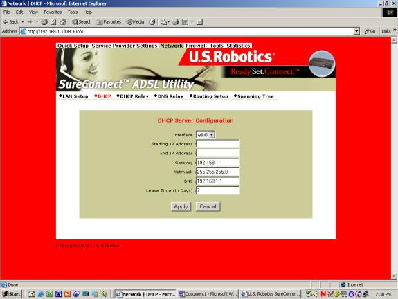
Configure the following parameters:
•Interface. LAN port that the DHCP server will support.
•Starting IP Address. First IP address in a block of addresses. The DHCP server uses this address in responding to a LAN port node’s DHCP request.
•End IP Address. Last IP address in a block of addresses. The DHCP server uses this address in responding to a LAN port node’s DHCP request.
•Gateway. IP address of the Default Gateway or Router that the node will use.
•Netmask. Subnet Mask for the LAN that the node will be on.
•DNS. Domain Name Server. The DNS that the node will use. DNS is a server with a database. The database translates a domain name into a corresponding IP address. For example, “USR.com” resolves into IP address 231.222.320.4. Communications over the LAN between the node and USR.com web site use this address.
•Lease Time. Number of days that the node can use a DHCP lease. Subsequently, you must renew the lease with the DHCP server.
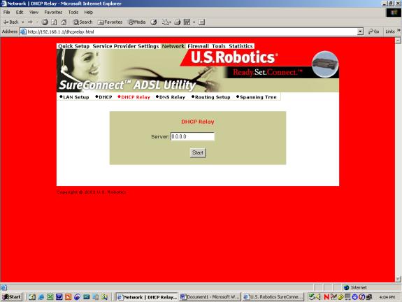
DHCP Relay
Suppose that a Dynamic Host Configuration Protocol (DHCP) server resides on a different LAN than the node broadcasting for DHCP service. Then the DHCP broadcast request must be forwarded across the router/WAN to a subnet where a DHCP server resides. The router must relay the DHCP request. DHCP relay assures that the requesting node receives an IP address that corresponds to the node’s subnet. The router must have a record of the DHCP server’s IP address.
With this address, the router can correctly direct the request to the appropriate DHCP server.
After you input the IP address into the menu, start the relay agent by clicking Start.
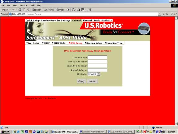
DNS Relay
The DNS Relay function supports forwarding of DNS requests from a LAN node to a known DNS server.
•Domain Name. Internet site address that the router is a group of (i.e. usr.com).
•Primary DNS Server. IP address of the Primary DNS that the router will use. Domain Name Server (DNS) is a server with a database. This server translates a domain name into the corresponding IP address. For example, USR.com resolves into IP address 231.222.320.4. Communications over the LAN between the node and web site USR.com use this address.
•Secondary DNS Server. IP address of the Secondary DNS that the router will use.
•Gateway. IP address of the Default Gateway the Router is to use.
•DNS Relay. Enabling or Disabling router ability to convey a DNS request from a LAN node.
To save and install DNS relay data…
- Input the data.
- Click Apply.
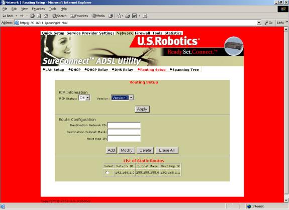
Routing Setup
A router forwards data packets between local area networks (LANs) or wide area networks (WANs). Based on routing tables and routing protocols, routers read the network address in each transmitted packet. Routers then decide where to send the packet. A router bases this decision on the best route. The Routing Setup menu allows the user to configure how the router forwards received IP packets.
RIP Information
Routing Information Protocol (RIP) is a routing protocol and is part of the TCP/IP suite. RIP determines a route based on the smallest hop count between source and destination. RIP determines the smallest hop count by communicating with other routers within the network. Only use RIP if the target router also utilizes RIP.
•RIP Status=On/Off selection.
•Version= Version 1 (RIP1) or Version 2 (RIP2). Should match RIP versions used by other routers in the network.
To save and install RIP data…
- Input the data.
- Click Apply.
Route Configuration
Use the Routing Setup area to add, delete or modify static routes. Static routes are permanent routes that the router stores. The router uses these routes when determining where to forward IP packets that it receives.
•Destination Network ID. IP address of the network that you’re defining in the table.
•Destination Subnet Mask. Network Subnet Mask of the defined entry in the table.
•Next Hop IP. IP address of the next router that will forward packets to the destination network.
•Add. Add information to the routing table.
•Modify. Modifies an entry. To modify an entry…
- From the List of Static Routes, select the route to modify. To do that, click Select next to the route you’re modifying.
- Then click Modify.
•Delete. Used to delete an existing entry. To delete…
- Select the route to modify from the List of Static Routes. Do that by clicking Select next to the route you’re deleting.
- Click Delete.
•Erase All. Erases all routes in the List of Static Routes. This feature won’t erase networks defined on interfaces of the router.
List of Static Routes
The list of networks known by the router. The list also includes the Next Hop to get to these networks. Static routes may be networks added statically or learned from other networks.
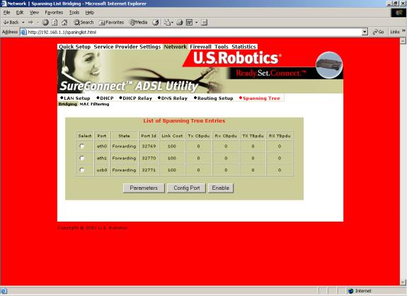
Spanning Tree-Bridging
Transparent bridges use the spanning tree algorithm to dynamically determine the best source-to- destination path. This algorithm avoids bridge loops (multiple paths linking one segment to another) within a network. The algorithm determines all redundant paths and makes only one of them active. The spanning tree protocol (STP) is part of the IEEE 802.1d standard.
List of Spanning Tree Entries
List all known router bridging ports and their current state.
To view the current state of the spanning tree bridge click Parameters. The following screen appears…
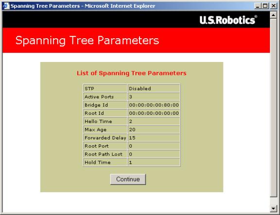
To close the screen, click Continue.
To configure a port, click Config Port. The following screen appears…
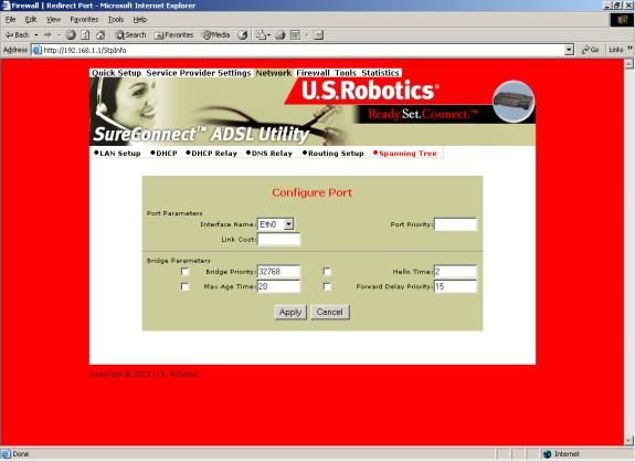
Port Parameters
•Interface Name. Router interface to be configured for spanning tree.
•Link Cost. Cost associated with that interface. Based on this cost, the bridge decides which link to forward data over. The options range from 0 to 65,535.
•Port Priority. Determines which port becomes the root port. Options range from 0 to 255.
Bridge Parameters
•Bridge Priority. Determines which bridge becomes the root bridge. Options range from 0 to 65,000.
•Max Age Time. All bridges in the bridged LAN use this timeout value. The root sets Max Age value. Options range from 1 to 60 seconds.
•Hello Time. Time interval between generations of configuration BPDUs (Bridge Protocol Data Units). The root generates configuration BPDUs. Options range from 1 to 10 seconds.
•Forward Delay Time. All bridges in the bridged LAN use this timeout value. The root sets the forward delay value. Options range from 1 to 200 seconds.
To configure port information…
1. Input the information.
2. Click Apply.
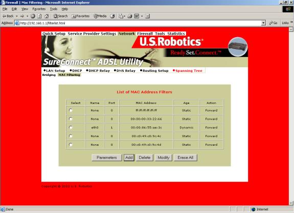
Spanning Tree - MAC Filters
The MAC address is a unique serial number burned into Ethernet adapters. This address distinguishes the network card from others. MAC Filters allow or reject WAN access for specific machines.
•List of MAC Address Filters. Known MAC addresses and the ports on which the router learned the addresses.
To view current filter states, click Parameters. The following screen appears…
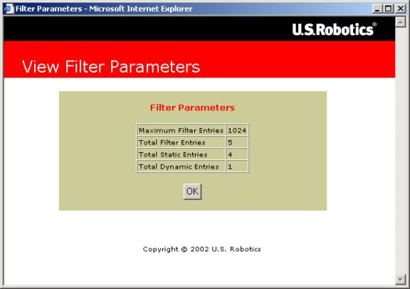
To close the screen, click OK.
To add a static MAC address to the table, click Add. The following screen appears…
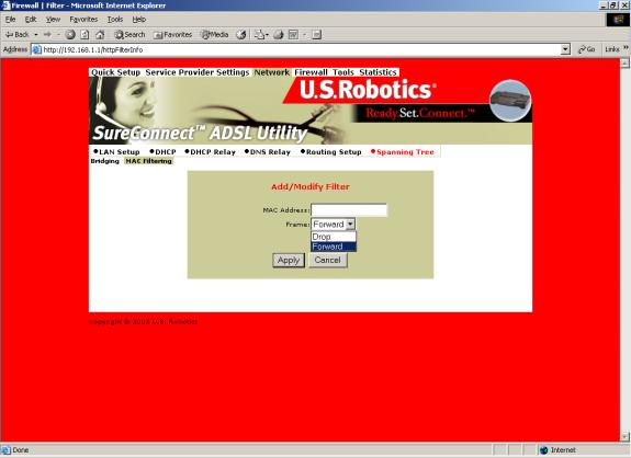
•MAC Address. Static MAC address to add to the table.
•Frame. What the router should do with a data frame from this MAC address. The options are Forward or Drop.
To set the Add/Modify Filter information…
- Input the information.
- Click Apply.
To delete an entry from the List of MAC Address Filters…
- Check the radio button to the left of the entry.
- Click Delete.
To modify a MAC address in the List of MAC Address Filters, or to make the address static…
- Check the radio button beside the entry.
- Click Modify.
- Proceed by following the same steps as in Add.
To erase all non-static MAC addresses, click Erase All.
Firewall Settings Page
IP Filtering
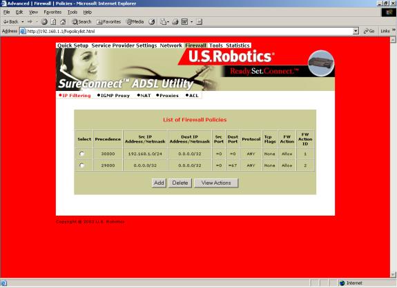
Click the IP Filtering header and view the List of Firewall Policies. The firewall’s factory-default setting is “Deny All.” The router includes factory-configured policies that allow access from LAN to WAN.
List of Firewall Policies
This screen displays the current list of firewall policies as defined in the router. The list appears in table form.
To remove an entry…
- Click the radio button beside the entry.
- Click Delete.
To add new policies, click Add. The following screen appears:
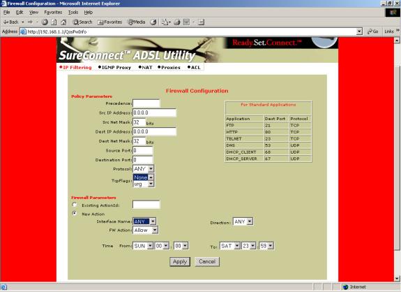
Policy Parameters
On the Firewall Configuration page, notice the header “Policy Parameters.” The Policy Parameters menu presents you with the following onscreen options …
• Precedence. Priority of the policy that you’re creating. Options range from 0 to 65,535. The lower precedence number takes priority.
• Src IP Address. Data source. Enter either a specific IP address or network address.
• Src Net Mask. Subnet Mask for the data’s network source. Options range from /12 (255.240.0.0) to /32 (255.255.255.255).
• Dest IP Address
. Data destination. Enter either a specific IP address or network address.
• Dest Net Mask. Subnet Mask for the data’s network destination. Options range from /12 (255.240.0.0) to /32 (255.255.255.255).
• Source Port. Transport layer source port. Options range from 0 to 65,535.
• Destination Port
. Transport layer destination port. Options range from 0 to 65,535.
• Protocol. IP protocols to be filtered. Options are: Any (all), TCP, UDP, ICMP, AH, ESP.
• TCP Flags. Filtering of the TCP Flags that control session setup and termination. Options are: None, urg (Urgent), ack (acknowledgement), psh (push), rst (reset), syn (synchronize), fin (finished).
Firewall Parameters
To edit a firewall parameter…
- Click the radio button beside “Existing ActionID.”
- Enter the “FW Action ID” to modify.
To create a new firewall parameter, Click the radio button beside “New Action.” The screen presents you with a number of options and sub-options…
- Interface Name. Name of the Interface to apply the parameter to.
- FW Action. How the system handles packets. Your sub-options include…
§ Allow. Permits packets to enter or leave the system.
§ Reset. Forces the TCP connection to reset.
§ Reject. Drops the packet and issues an “unreach host” ICMP error.
§ Deny. Drops the packet.
- Direction. Specifies whether the action applies to incoming, outgoing, or both incoming and outgoing traffic. Options are: Any, In, Out.
- Time. The parameter applies during the time period that you specify. Click the start (From) day, time and stop (To) day and time.
To save and install firewall configuration data…
- Input the data.
- Click Apply.
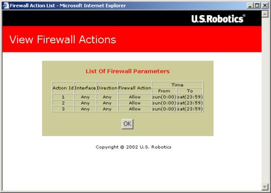
NOTICE. Check your firewall configuration data. See View Actions at the top menu. There, you’ll find a selection List of Firewall Policies. This selection summarizes the action that you entered for each parameter. When you click View Actions, the following screen appears.
IGMP Proxy
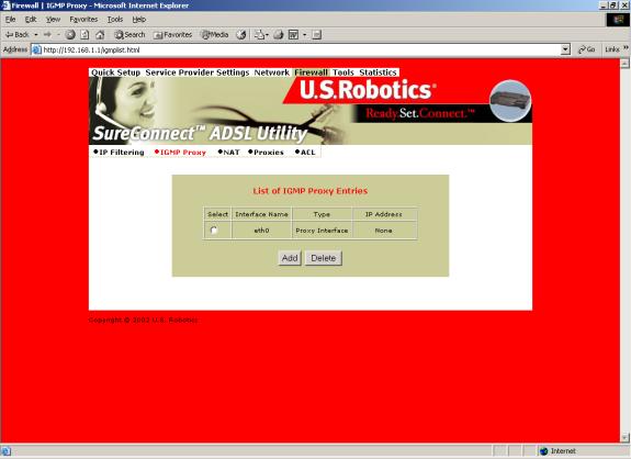
Click the IGMP Proxy radio button and view the List of IGMP Proxy Entries.
List of IGMP Proxy Entries
This screen displays a list of IGMP Proxy entries.
IGMP (Internet Group Membership Protocol) is a protocol. IP hosts use IGMP to report their multicast group memberships to immediately nearest routers.
To remove an entry…
- Click the radio button beside the entry.
- Click Delete.
To create a new IGMP Proxy entry, click Add. The IGMP Proxy Configuration screen appears…
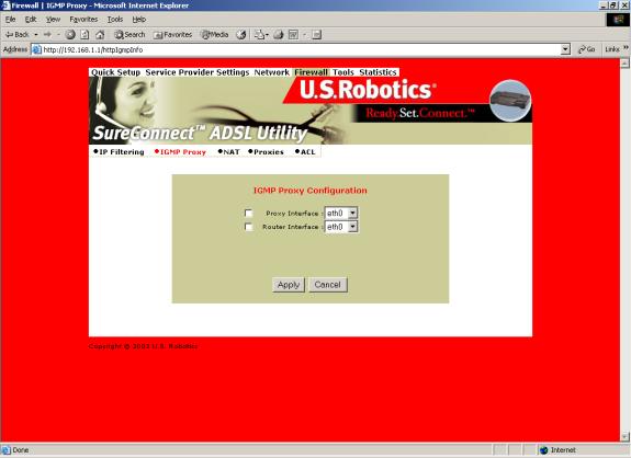
IGMP Proxy Configuration
On the IGMP Proxy configuration Screen, follow these steps to set up your IGMP proxy…
- Select Proxy interface, router interface, or both: Check the box next to the interface.
- Use the pull-down menu to the right to select the eth, usb, atm, or ppp Interface.
To save and install IGMP Proxy Configuration data…
- Input the data.
- Click Apply.
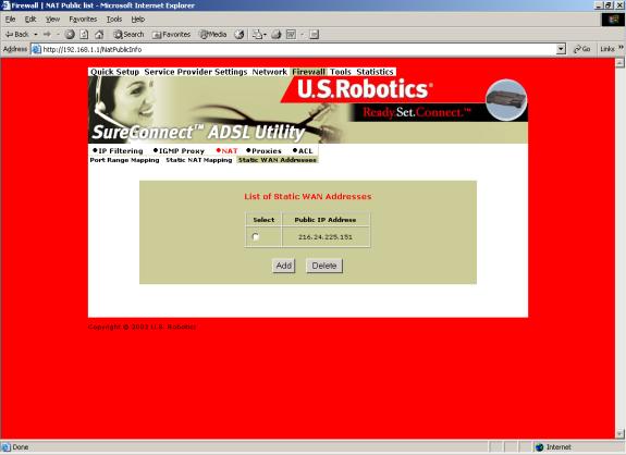
NAT=>List of Static WAN Addresses
From the List of Static Wan Addresses menu, you can remove or add entries. To remove an entry…
- Click the radio button beside the entry.
- Click Delete.
To create a new Static WAN Address entry, click Add. The Static WAN Address Configuration screen appears…
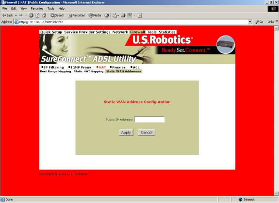
NAT=>Static WAN Address Configuration
Public IP Address. Public IP address that the router uses when translating network addresses.
To save and install Static WAN Address Configuration data…
- Input the data.
- Click Apply.
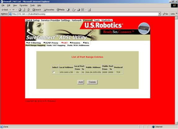
NAT=>Port Range Mapping
Click the NAT header and view the List of Port Range Entries. NAT port range mapping allows the router to map public addresses and ports to private addresses and ports.
List of Port Range Entries
NAT stands for Network Address Translation. NAT enhances the power of Port Range Mapping. Together, they can map a local IP address and port to a public IP address and port.
To remove an entry…
- Click the radio button beside the entry.
- Click Delete.
To create a new Port Range entry: Click Add on the top screen. The Port Range Configuration screen appears…
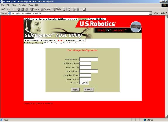
NAT=>Port Range Configuration
To add a Static NAT entry, set the following parameters…
- Public Address. Set the public, destination IP address inside a packet header. The router will map or redirect packets with the address that you specify.
- Public Port From. Set the first (From) port of the public address that the router maps or redirects. Options range from 1 to 65,535.
- Public Port To. Set the last (To) port of the public address that the router maps or redirects. Options range from 1 to 65,535.
- Local Address. Set the IP address of a machine on the local LAN. The router directs packets to this address.
- Local Port From. Set the first (From) port of the local address that the router uses. Options range from 1 to 65,535.
- Local Port To. Set the last (To) port of the local address that the router uses. Options range from 1 to 65,535.
- Protocol. Set protocol. Your protocol setting applies to the other parameters on this page. Your options are TCP or UDP port numbers.
To save and install Port Range Configuration data…
- Input the data.
- Click Apply.
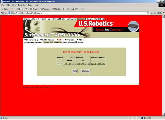
NAT=>Static NAT Mapping
Static Network Address Translation (NAT) maps multiple local IP addresses to a public IP address.
List of Static NAT Configuration
From the List of Static NAT Configuration menu, you can remove or add static NAT entries. To remove a entry…
- Click the radio button beside the entry.
- Click Delete.
To create a new Static NAT Configuration entry, click Add. The Static NAT Configuration screen appears…
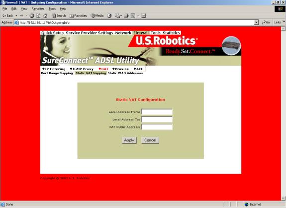
NAT=>Static NAT Configuration
To add a Static NAT entry, set the following parameters…
- Local Address From. First address in a range of local IP addresses. The router maps these addresses to the public IP address.
- Local Address To. Last address in a range of local IP addresses. The router maps these addresses to the public IP address.
- NAT Public Address. Public address. The router maps local addresses to this public address.
To save and install Static NAT Configuration data…
- Input the data.
- Click Apply.
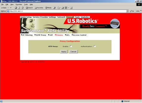
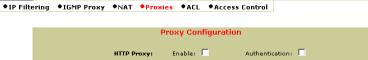
Proxy Configuration
Proxy Services are specialized application programs. These programs accept users’ requests from LAN clients for Internet services like HTTP. On behalf of LAN clients, proxy services also set up connections to WAN servers. A proxy server authenticates against the user database (Access Control). The proxy server filters a request against the Access Control List (ACL). Then the server forwards the request to actual services. Proxy Servers are application specific. Each application needs its own proxy server.
To save and install proxy configuration data…
- Click the radio button beside the HTTP proxy that you want to enable. (The illustration above doesn’t show proxy radio buttons.)
- Click Enable beside HTTP Proxy.
- Click Authentication. Clicking this box authenticates the user during the HTTP Proxy.
- Click Apply.

ACL (Access Control List)
The ACL List screen displays currently configured Access Control Lists (ACL).
To remove an ACL List entry…
- Click the radio button beside the entry.
- Click Delete.
To create a new ACL entry, click Add from the top screen. The following screen appears…
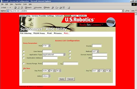
Proxy Parameters
| Term |
Definition |
|
Port |
Proxy port. |
|
Priority |
Priority of the policy you’re creating. Options range from 0 to 65,535. |
|
User Name |
A configured user in the router’s internal database. You must configure users through the Access Control Menu. |
|
Application Type |
HTTP application file type (MIME) to filter or proxy. Options are… •application (all), •image (all), •video (all), •audio (all), •application/octet-stream, •audio/x-wav, •audio/x-mpeg, •image/jpeg, •video/mpeg. |
|
Destination Address |
Destination IP address of the FTP or HTTP server on the WAN. |
|
Source Range |
Local IP address range that the rule applies to. “From” is the first IP address in the range. “To” is the last IP address in the range. |
|
Domain Name |
Address of an Internet site to filter. |
|
Day From/To |
Set the effective start (From) day and time for the policy. Set the effective stop (To) day and time for the policy. |
|
Action |
Specifies how the ACL deals with requests to the policy. Options are Allow or Deny. |
To save and install Access List configuration data…
- Input the data.
- Click desired radio button options. The router only applies options that you select.
- Click Apply.
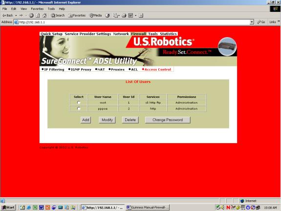
Access Control
List of Users.
The List of Users allows you to delete or authorize user access privileges. To set up a new user account, you assign a username and password. With the username and password, you can open a new account with either administrative or ordinary privileges.
To delete a user account…
- Click the radio button beside the user entry.
- Click Delete.
To create a new user entry…
- Click Add on the top-level, List of Users screen. The following screen appears…
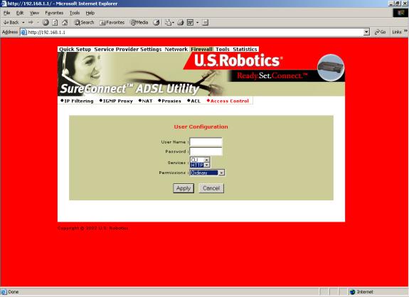
User Configuration
User Configuration Parameters
| User Account Data Term |
Definition |
|
Username |
Configurable username with up to 19 characters. |
|
Password |
Configurable user password with up to 19 characters. |
|
Services |
Services available to the user. Options are CLI, HTTP, and FTP. To select all, perform a <SHIFT> right click. To make multiple selections, <CTRL> click on each selection. |
|
Permissions |
Administration access or Ordinary access. |
To save and install User Configuration data…
- See the table above. Input the user account data.
- Click Apply.
To modify a User entry…
- Click the radio button next to the user to be modified.
- Click Modify from the top-level, List of Users screen. The following screen appears...
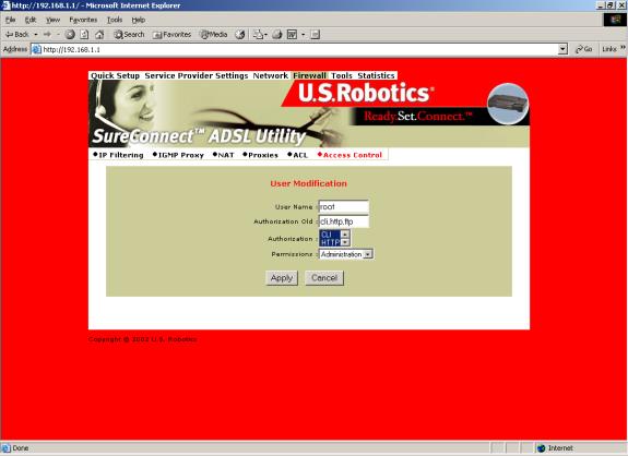
User Modification
User Account Modification Parameters
| User Account Data Term |
Definition |
|
User Name & Authorization Old |
User account that you’re modifying. You can’t change these settings. |
|
Authorization |
Select the new authorization level for this user. Your options are CLI, HTTP, and FTP. To select all, perform a <SHIFT> right click. To make multiple selections, <CTRL> click on each selection. |
| Permission |
Select the new Permission level for this user. Choose Administration access or Ordinary access. |
To save and install user account modification data…
- Input user account modification data.
- Click Apply.
To change a user’s password,,,
- Click the radio button next to the appropriate user account.
- Click Change Password from the top-level, List of Users screen. The following screen appears…
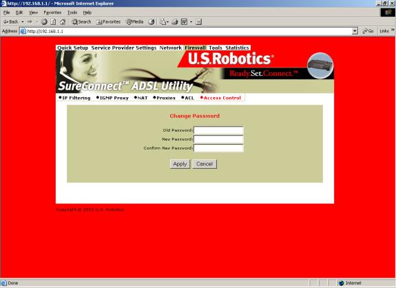
Change Password
User Password Change Parameters
| Password Data Term |
Definition |
|
Old Password |
Enter the user’s old password. |
|
New Password |
Enter the user’s new password. |
| Confirm New Password |
Confirm a correct entry by reentering the user’s new password. |
To save and install User Modification Configuration data…
- Input the data.
- Click Apply.
Tools Page
SNMP
Simple Network Management Protocol (SNMP) is a software component that resides in a network device. SNMP responds to requests for information and action from a network management station. Within the network device, an object-like format called a Management Information Base (MIB) stores the information exchanged during SNMP.
SNMP=>System
The System function displays the SNMP parameter as assigned by the SNMP Administrator. Modify the default settings by following these steps...
- Click Modify.
- Enter your changes.
- Click Apply.
NOTICE. To stop the SNMP agent, click Stop. The Stop button toggles to become the Start button. After the process ends, you can start the agent by clicking Start.
Configure the SNMP listening port by following these steps...
- Click Stop to stop the agent.
- Click Configure SMNP Agent.
- Enter your changes.
- Click Apply.
- Restart the agent.
SNMP=>Trap
Set the agent to report up or down status by following these steps...
- Select the version of SNMP manager that the community is running.
- Click Modify.
- Enter the SNMP manager's IP address into its community name.
- Select Enable for that status option.
- Click Apply.
SNMP=>Community
Set the SNMP manager's IP address and community name for SNMP message exchange by following these steps...
- Click Configure Community.
- Enter your changes.
- Click Apply.
Diagnostic
The Diagnostic feature can generate ATM or IP traffic for troubleshooting or testing your router’s configuration. Sometimes the request for a response fails. The failure may be due to your ISP’s disabling its equipment from responding to these requests. The ISP may disable responses for many reasons, including your security.
Diagnostic=>OAM Loopback
OAM Loopback generates two forms of ATM frames for testing the integrity of your ATM circuit. F5 Segment (F5 SEG) frames transmit, but the ISP’s ATM switch doesn’t loop them back. F5 End-to-End (F5 ETE) frames transmit and the ISP’s ATM switch replies.
To Start the OAM Loopback Test…
- Select the frame type.
- Enter an existing PVC (VPI/VCI) for the F5 ETE frames.
- Enter the ATM switch loopback ID for the F5 ETE frames.
- Click the Start Loopback to begin the test.
- After the test completes, a screen reports results. Click Back to return to the Diagnostic screen.
IP Address Ping Test
To Start the Address Ping Test…
- Enter the IP of the network device that accepts ICMP packets.
- Click Ping. If someone disabled ICMP packet forwarding on the device, the Ping will fail.
Save and Restart
Whenever you make changes to the router’s configuration, the router saves the changes in temporary memory storage. A power loss or power switch disconnection can cause the router to lose changes. To make permanent changes, save changes and restart the router.
After you click Save, the router returns to the Save and Restart screen. You may reboot your router by clicking Restart. Another way to reboot is to turn the router off and on from the router’s power switch.
CAUTION. The Restart button doesn’t return you to the Save and Restart menu. You can return by either of two methods: Click the browser’s Back Arrow key. Or reenter the router management IP address on your browser’s address line.
Restore and Restart
The Restore and Restart option returns the router’s configuration to factory default settings.
CAUTION. During restoration to default settings, the router loses all your changes. After the restoration process completes, you must reenter changes.
To erase the current router configuration…
- Click Restore.
- Click Restart.
- Allow the router a few minutes to restore to factory settings.
- Enter the router management IP address in the address line of your browser. The router main menu appears.
Date and Time
To set the router's date and time input...
- Key in your entry for the "Date" field. Use the format MM:DD:YYYY.
- Key in your entry for the "Time" screen. Use the format HH:MM:SS.
- Click Apply.
Version
Click the Version option to see the router firmware version.
Statistics Page
ADSL Link Status
Displays ADSL line settings and connection status
Status Term |
Meaning |
| ADSL Line Status |
Displays the current ADSL line status |
| ADSL Standard |
Displays the ADSL standard within the current configuration. The standards are: MULTI, T1.413, G.dmt, and G.Lite. |
| UpStream |
Displays the upstream data rate, as negotiated by DSL link (Kb/s) |
|
DownStream |
Displays the downstream data rate, as negotiated by DSL link (Kb/s) |
|
Attenuation |
Displays the current attenuation in decibels |
|
SNR Margin |
Displays the current SNR margin in decibels |
| HEC Count |
Displays the number of ATM cells received with errors since start of link. |
| Firmware |
Displays the version number of the firmware |
| 15 min ES Counter |
Displays the number of errors per second for the current 15-minute period |
|
CRC Errors |
Displays the number of cyclical redundancy check errors per second since training |
| 1 day ES Counter |
Displays the number of errors per second for the current day |
System Statistics
Interface Statistics
Interface Statistics displays the statistics for all interfaces.
| Screen Term |
Meaning |
Interface Name |
Name of the interface |
|
Admin Status |
Indicates whether the interface is up or down |
|
Octets In |
Number of received octets (in bytes) |
|
Unicast PktsIn |
Number of received unicast packets |
|
Broadcast PktsIn |
Number of received broadcast packets |
|
Discards In |
Number of received and discarded packets |
|
Errors In |
Number of received errors |
|
Octets Out |
Number of transmitted octets (in bytes) |
|
Unicast PktsOut |
Number of transmitted unicast packets |
|
Broadcast PktsOut |
Number of transmitted broadcast packets |
|
Discards Out |
Number of transmitted and discarded packets |
|
Errors Out |
Number of transmitted errors |
TCP-IP
The TCP-IP screen displays IP, UDP, TCP and ICMP statistics.
DHCP Lease
The DHCP-Lease displays names of devices on the network. These devices received an IP address from the router’s DHCP server address pools. The screen also displays how long you can use this IP.
ATM Statistics
The ATM Statistics Screen displays traffic statistics for Adaptation Layer 5 of the ATM protocol and encapsulation.
AAL5 Statistics
The AAL5 Screen totals transmitted and received cells. The screen also reports total CRC (Cyclical Redundancy Check) errors.
Subnetwork Dependent Convergence Protocol (SNDCP)
For the permanent virtual circuit (PVC), the SNDCP Screen organizes packet information by Encapsulation Method.
Firewall Statistics
The Firewall Statistics Screen maintains flow-based statistics for incoming, outgoing and dropped packets. Flow statistics describe the source address, source port, destination address, destination port and protocol.
Traffic Statistics
The Traffic Statistics Screen displays data about inbound, outbound and dropped packets.
HTTP Proxy Statistics
The HTTP Proxy Statistics screen maintains data on the user. Software collects statistics for incoming packets, outgoing packets, incoming bytes and outgoing bytes. If you disable authentication, this screen displays statistics on the general user.